Boiler and Engine Room Ballast Pumps

Hi All,

I'm doing some research on the pumping systems of the ship. I read Leading Fireman Frederick Barrett's British Testimony, and he said this:

2024. Then what was the next order?
- He asked me to lift the manhole plate off.

2025. Where was the manhole plate?
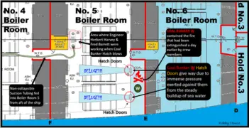
- On the starboard side of No. 5 section.

2026. When the plate was in position what was it - closed?
- It is something you lift up to get at the valves. I do not know what valves it is. It is just like a hole in this table. You lift it off to get to the valves to turn on the pumps or something.

2027. Is it in the floor?
- Yes.

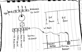
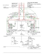
If I recall correctly, someone testified that the Engineers managed to redirect the pumps to pump out the incoming water, probably out the discharge washports in the Turbine Room? (Based on Lifeboat 13's testimony of a large volume of water being pumped out the side) But How did they do this? It looks like something with the Circulating Pumps were involved.
1650642246631.jpg


Thanks for any help, I appreciate it.
 
It was common in British ships right up to when I went to sea in the 60s to site the valves below the plates to more or less ensure that you couldn't read the valve tally in the filthy bilge area, and also quite a few skinned shins from stepping into one which had been left open. It was also difficult to trace the systems under the plates in the stygian gloom between the underside of the plates and the tank top. We had no piping schematics on any ship I was on until Japanese ships made their entrance.

What a sea change! Really well built, well documented and most valves mounted above the plates at around waist and chest height. You could see the demise of British Shipbuilding staring you in the face...

I have some drawings of the Olympic class piping - some modern CAD and I'd love to know who drew them - and some copies of originals from H&G which I cannot divulge but I guess could hand draw snippets.

However, basic pumping and piping systems haven't changed much, other than the pumps being EMD whereas Titanic's were of course steam.

A water pump such as a bilge and/or ballast pump has a suction valve chest on one side and a discharge valve chest on the other. Most bilge pumps were - and still are in many cases - positive displacement bucket pumps.

I know Titanic had pumps in the boiler rooms for local pumping, and they should have had a direct and engineroom bilge line from each BR space to the suctions on the main ER pump. The reason I say should is because it would have negated having to open WT doors in order to get a suction hose through.

A bilge pump would have -
Suction Side:
1. Sea suction
2. Engineroom bilge line suction
3. Direct bilge line suction
4. Oily bilge line suction
5. Ballast system

Discharge side:
1. Overboard
2. To ballast system
3. To Oily Water separator and bilge tanks (modern ships under MARPOL 78)

All you had to do to pump the ER bilges over the wall was crack the bilge suction NR valve on top of the vertical bilge pipe in whatever bilge well you were pumping out, crack open the sea suction to give the pump something to draw on until it gets suction on the well, open the overboard discharge valve, drain the pump cylinders of water with the steam valve cracked open and away she goes!

You then fiddle with the bilge well suction valve until it rattles (showing that it's drawing water) and close the sea suction once water's coming through the pump.

That's all there is to it and the engineers would do it as the stokehold crews were there to stoke boilers - enough of a job in itself!

If you want drawings I have them from both new ships - not really any different - and one from Titanic. Depending on their size they may go via this site.

Incidental, my theory on the rush of water that nearly sank Boat 13 wasn't the bilge, the lines are quite small. It's right at the spot where the Auxiliary Condenser overboard is (a large volume of water) which was started when they changed over the dynamos from the main to auxiliary systems.

I mention this in one of my 'Ship Starting' articles which you can find here -


I've updated it but not posted to the site yet, but you can get a fair bit of engineering info from this revision.
That was a good paper. I downloaded it to read it more in depth when I get the time. But I have one question. You mentioned shore power in a few spots. I've read in various articles/places that Titanic didn't have a shore power connection and in the 1912 time frame era shore power was an almost unheard of thing. But I don't know how things really worked back then as far as that goes. I'm sure they had to have some arrangment in the shipyards but not sure about the various ports. Do you have any more info on the shore power for Titanic/Olympic? Just curious. Cheers.
 
It was common in British ships right up to when I went to sea in the 60s to site the valves below the plates to more or less ensure that you couldn't read the valve tally in the filthy bilge area, and also quite a few skinned shins from stepping into one which had been left open. It was also difficult to trace the systems under the plates in the stygian gloom between the underside of the plates and the tank top. We had no piping schematics on any ship I was on until Japanese ships made their entrance.

What a sea change! Really well built, well documented and most valves mounted above the plates at around waist and chest height. You could see the demise of British Shipbuilding staring you in the face...

I have some drawings of the Olympic class piping - some modern CAD and I'd love to know who drew them - and some copies of originals from H&G which I cannot divulge but I guess could hand draw snippets.

However, basic pumping and piping systems haven't changed much, other than the pumps being EMD whereas Titanic's were of course steam.

A water pump such as a bilge and/or ballast pump has a suction valve chest on one side and a discharge valve chest on the other. Most bilge pumps were - and still are in many cases - positive displacement bucket pumps.

I know Titanic had pumps in the boiler rooms for local pumping, and they should have had a direct and engineroom bilge line from each BR space to the suctions on the main ER pump. The reason I say should is because it would have negated having to open WT doors in order to get a suction hose through.

A bilge pump would have -
Suction Side:
1. Sea suction
2. Engineroom bilge line suction
3. Direct bilge line suction
4. Oily bilge line suction
5. Ballast system

Discharge side:
1. Overboard
2. To ballast system
3. To Oily Water separator and bilge tanks (modern ships under MARPOL 78)

All you had to do to pump the ER bilges over the wall was crack the bilge suction NR valve on top of the vertical bilge pipe in whatever bilge well you were pumping out, crack open the sea suction to give the pump something to draw on until it gets suction on the well, open the overboard discharge valve, drain the pump cylinders of water with the steam valve cracked open and away she goes!

You then fiddle with the bilge well suction valve until it rattles (showing that it's drawing water) and close the sea suction once water's coming through the pump.

That's all there is to it and the engineers would do it as the stokehold crews were there to stoke boilers - enough of a job in itself!

If you want drawings I have them from both new ships - not really any different - and one from Titanic. Depending on their size they may go via this site.

Incidental, my theory on the rush of water that nearly sank Boat 13 wasn't the bilge, the lines are quite small. It's right at the spot where the Auxiliary Condenser overboard is (a large volume of water) which was started when they changed over the dynamos from the main to auxiliary systems.

I mention this in one of my 'Ship Starting' articles which you can find here -


I've updated it but not posted to the site yet, but you can get a fair bit of engineering info from this revision.
Thanks Steven! I really appreciate it.
I was watching a video on an Illegal practice known as "Bilge Dumping" and I noticed that the Olympic Class had a bilge pump. Did they do the same thing?

And I'd love to have the drawings please, if its alright.
That was a good paper. I downloaded it to read it more in depth when I get the time. But I have one question. You mentioned shore power in a few spots. I've read in various articles/places that Titanic didn't have a shore power connection and in the 1912 time frame era shore power was an almost unheard of thing. But I don't know how things really worked back then as far as that goes. I'm sure they had to have some arrangment in the shipyards but not sure about the various ports. Do you have any more info on the shore power for Titanic/Olympic? Just curious. Cheers.
I read an issue of the Engineer or Engineering (can't remember) that mentioned this, and then talked about the 4 Electric Engines aft, and thus not needing to be powered by shore power.

I've seen a plan of the H&W shipyards, but I forget where it was, unfortunately. If you want I can look.
 
"I read an issue of the Engineer or Engineering (can't remember) that mentioned this, and then talked about the 4 Electric Engines aft, and thus not needing to be powered by shore power.

I've seen a plan of the H&W shipyards, but I forget where it was, unfortunately. If you want I can look."

I've forgotten what I read about it. I know they had power to build the ships and repair them in the shipyards. Could have been as simple as lots of extension cords. But probably also had portable power panels. 1912 was still early in the electrification of the world. My mom told me when she was little alot of the farms/ranches still didn't have electricity untill almost WW2 where she grew up. Titanic used boiler No. 1 I believe it was as sort of a donkey boiler to keep the ship powered while in port. I was just wondering if they had an alternant shore power connection that maybe Stephen ran across. The other issue was DC vrs AC. They would have needed DC power or some really large rectifiers because I believe by 1912 New York was already an AC system. Cheers.
 
That was a good paper. I downloaded it to read it more in depth when I get the time. But I have one question. You mentioned shore power in a few spots. I've read in various articles/places that Titanic didn't have a shore power connection and in the 1912 time frame era shore power was an almost unheard of thing. But I don't know how things really worked back then as far as that goes. I'm sure they had to have some arrangment in the shipyards but not sure about the various ports. Do you have any more info on the shore power for Titanic/Olympic? Just curious. Cheers.
No Steven I don't, other than the one in ET from Sam Halpern I think, on the electrical systems of the ship, though whether it includes shore power I'd have to have a look.
Whilst the ship was in build, it was all "open sky" until they started to plate the decks over, after which they would have had to include a necklace of lighting I would think, and that was the case in my early days in shipbuilding in river valleys. That's all gone now - in Korea (SHI) I had a look round their building shops and the deckhead was upside down so that strip lights, cabling etc could all be done below you and not having to reach up from staging from below. Imagine turning your house upside down to get at the ceiling light fittings! It was all painted, all cabling, trunking and equipment was fitted in upside down. Once finished the crane inverted it, travelled to wherever the the deck below was, and then welded to it. Remarkable compared to the mass of staging in British yards at the time.
I would imagine that the lighting in outfit was supplied from ashore via a number of rated cables and into a number of "porcupines" which is a manifold with a number of sockets in it pretty much like an extension is, but with a heavy cable and of course watertight fittings. It's still like that in some shipyards - notably in China where I was client engineer on an FPSO newbuild.
For a ship in drydock they would need either shore power if available - I'm pretty sure it would have been - or they had to leave a boiler steaming in order to provide power for at least one of the auxiliary dynamos in say Olympic when she was in service. I believe the Olympic Class were single wire with a return through the plating like a car is, but not absolutely sure of that, as it seems a bit antiquated. It's mentioned in a fascinating tome I have called Sothern's MArine Engineering, dated 1927, but thought to be a possible source of condenser corrosion! I would think it acted like a battery and dissolved your condenser, and it seems it was changed to two wire insulated with an earth to the hull steel. I can't see any reason for not supplying a shore connection, but who knows in those days? It wasn't difficult, but it only gave you a certain number of wiggly amps, and that's still the case today, where it normally ties into the switchboard on the emergency bus. On a tanker it's about 200-300A if I remember correctly, and only used for lighting - any attempt to start an induction motor tends to make the ship go dark and quiet...
As for ports, it's not available though there are moves afoot to provide it in cruise terminals owing to the amount of exhaust gas these monsters pump out into the surrounding areas. The idea is to either supply it from the national grid, or purpose build a gas fired power station. Powership (a Turkish outfit) has an innovative method where they provide a Powership for you with the requisite number of MW and all the terminal has to do is feed it with re-gassed LNG. Pretty good, I surveyed one a few years ago in Indonesia.
Hope that fills in a few holes!
 
Thanks Steven! I really appreciate it.
I was watching a video on an Illegal practice known as "Bilge Dumping" and I noticed that the Olympic Class had a bilge pump. Did they do the same thing?

And I'd love to have the drawings please, if its alright.

I read an issue of the Engineer or Engineering (can't remember) that mentioned this, and then talked about the 4 Electric Engines aft, and thus not needing to be powered by shore power.

I've seen a plan of the H&W shipyards, but I forget where it was, unfortunately. If you want I can look.
Bilge dumping is generally frowned upon since the advent of MARPOL but I'm sure there are some hick outfits that still take the chance. It's certainly not done on modern ships of the big companies that operate tankers, bulkers and containerships.
The Olympic Class certainly had bilge pumps and all ships do, even your private sailing boat! There has to be a way to get water and oil out of the bilge, and that's what the pumps do.
I've uploaded what I've got in the way of piping, but one of the whole ship FW system is too big for the portal. I've included a nice one from Robby House regarding the removal of plates to get at the bilge valves, and one hand drawn that I did to explain how I reckoned they were using the suction hose they had to open the WT doors for. The others are steam piping and feed water - nicely drawn, wish I knew who by...
 

Attachments

  • Bilge suctions.png
    Bilge suctions.png
    185.8 KB · Views: 192
  • Bilge schematic.pdf
    1.5 MB · Views: 154
  • Typical bilge suction.jpg
    Typical bilge suction.jpg
    329.3 KB · Views: 171
  • Feed Water.jpg
    Feed Water.jpg
    160.4 KB · Views: 165
  • Steam 2.jpg
    Steam 2.jpg
    156.4 KB · Views: 163
  • Steam.jpg
    Steam.jpg
    200 KB · Views: 179
No Steven I don't, other than the one in ET from Sam Halpern I think, on the electrical systems of the ship, though whether it includes shore power I'd have to have a look.
Whilst the ship was in build, it was all "open sky" until they started to plate the decks over, after which they would have had to include a necklace of lighting I would think, and that was the case in my early days in shipbuilding in river valleys. That's all gone now - in Korea (SHI) I had a look round their building shops and the deckhead was upside down so that strip lights, cabling etc could all be done below you and not having to reach up from staging from below. Imagine turning your house upside down to get at the ceiling light fittings! It was all painted, all cabling, trunking and equipment was fitted in upside down. Once finished the crane inverted it, travelled to wherever the the deck below was, and then welded to it. Remarkable compared to the mass of staging in British yards at the time.
I would imagine that the lighting in outfit was supplied from ashore via a number of rated cables and into a number of "porcupines" which is a manifold with a number of sockets in it pretty much like an extension is, but with a heavy cable and of course watertight fittings. It's still like that in some shipyards - notably in China where I was client engineer on an FPSO newbuild.
For a ship in drydock they would need either shore power if available - I'm pretty sure it would have been - or they had to leave a boiler steaming in order to provide power for at least one of the auxiliary dynamos in say Olympic when she was in service. I believe the Olympic Class were single wire with a return through the plating like a car is, but not absolutely sure of that, as it seems a bit antiquated. It's mentioned in a fascinating tome I have called Sothern's MArine Engineering, dated 1927, but thought to be a possible source of condenser corrosion! I would think it acted like a battery and dissolved your condenser, and it seems it was changed to two wire insulated with an earth to the hull steel. I can't see any reason for not supplying a shore connection, but who knows in those days? It wasn't difficult, but it only gave you a certain number of wiggly amps, and that's still the case today, where it normally ties into the switchboard on the emergency bus. On a tanker it's about 200-300A if I remember correctly, and only used for lighting - any attempt to start an induction motor tends to make the ship go dark and quiet...
As for ports, it's not available though there are moves afoot to provide it in cruise terminals owing to the amount of exhaust gas these monsters pump out into the surrounding areas. The idea is to either supply it from the national grid, or purpose build a gas fired power station. Powership (a Turkish outfit) has an innovative method where they provide a Powership for you with the requisite number of MW and all the terminal has to do is feed it with re-gassed LNG. Pretty good, I surveyed one a few years ago in Indonesia.
Hope that fills in a few holes!
Thanks for the reply. Most interesting. Yes everything I've read for the DC system aboard the the Olympic class ships used the ships hull/metal as the return leg. It's an economical solution. Would be so even today especially with the price of wire. I imagine when in the ship yards there were extention cords running everywhere for lights and tools. Same as a power plant during an outage. Temp power panels and cords everywhere. Potable generators too. I will have to go look up power ships. Never heard of them before. Sounds interesting. I don't remember the particulars but I was told that one of our aircraft carriers once backfed the grid to power a city during a grid failure. Think it was in WA or OR. Cheers.
 
Bilge dumping is generally frowned upon since the advent of MARPOL but I'm sure there are some hick outfits that still take the chance. It's certainly not done on modern ships of the big companies that operate tankers, bulkers and containerships.
The Olympic Class certainly had bilge pumps and all ships do, even your private sailing boat! There has to be a way to get water and oil out of the bilge, and that's what the pumps do.
I've uploaded what I've got in the way of piping, but one of the whole ship FW system is too big for the portal. I've included a nice one from Robby House regarding the removal of plates to get at the bilge valves, and one hand drawn that I did to explain how I reckoned they were using the suction hose they had to open the WT doors for. The others are steam piping and feed water - nicely drawn, wish I knew who by...
Thanks for the prints. I like them. Yes besides dity bilge water another problem is invasive species getting tranported and dumped where they shouldn't be. But that's not just a problem with large ships. Our desert lakes and rivers have been contamenated with invassive species such as the quagga (sp) mussles. Transported by all things as bass boats pumping out the bilge. Lake Mead and the lower Colorado river are full of them now. They gummed up our river water pumps at the plant I used to work at.
A bit of trivia I ran across reading some old engineering documents from the days of Titanic. Up until the advent of the large ocean liners it was standard practice of the Royal and US Navies to size the bilge pumps at least equal to the capacity of the feedwater pumps. That's what the merchant ships used also.There was no board of trade standards and they left it up to the ships designers. But as the ships got so big they had to add bilge pumping capabilty. The paper mentioned a formula they came up with but I couldn't find it anywhere. Probably used some sort of tonnage/displacement number but not sure about that. Cheers.
 
I've a question relating to the capability of the pumping system in slowing down the rate of flooding.

Could any of the pumps extract water from any given boiler room in parallel with other pumps? More specifically, could the two pumps in boiler room 3 extract water from boiler room 5 in addition to the pump in boiler room 5? Also could the pump in boiler room 6 which was quickly flooded and presumably underwater, be used to pump water out of boiler room 5?

I noticed from the plan of the tank top that no pumps were located in boiler room 4, so presumably it had to rely on the pumps in neighbouring boiler rooms.

Incidentally what has happened to the detailed plans of each deck, do we have to purchase them now?
 
Good day to you Mr. Chappell,


Except for the forepeak tank and aft-peak tank, the remaining 14 watertight compartments all had drain pots connected to all ballast and bilge pumps throughout the ship. It is true that all watertight compartments (such as the number one, number two, number 3 cargo holds, boiler room number 6, boiler room number 4, boiler room number 1, the electric engine room and the two propeller tunnel rooms) had to rely on the ballast and bilge pumps of the other compartments.


The Titanic had 5 ballast pumps (which moved 4 tons a minute, they were designed to move fluids between tanks and evens the ship in cases of a serve list) and 3 bilge pumps (which moved 2.5 tons a minute, they were designed as scavenger pumps to keep slow inflows of water under control and to get it overboard). With the rate of flooding the Titanic had all pumps would be overwhelmed the pumps. It is believed that the pumps were activated on order of chief engineer Bell in the first ten minutes of the sinking. No matter what pumps the Olympic class which were available at the time, they would have been unable to safe the ship.


I hope this might helps.


Yours sincerely,


Thomas
 
Thomas

So are you saying the valves could be arranged so all the pumps could be used in parallel (simultaneously) to pump the flood water out of any chosen compartment? So for example 5 x 5 + 3 x 2.5 = 32.5 tons/min of water could be pumped from lets say, Boiler room 5 (bearing in mind that the pumps in boiler room 6 were quickly underwater).

What has confused me is this video by Bill Sauder who says that most of the pumps couldn't draw water from the head of the ship were the flooding was. He also mentions running extra lines to bring more pumps on line. This would suggest to me that they couldn't be operated in parallel and the pipework was arranged so only pumps near to the flooding compartments could be used.

There might be another reason why the pumps near the engine room couldn't be used to reduce this type of flooding, because a vacuum pump can't suck more than atmospheric pressure which is equivalent to about 10 metres (33ft). Hence even if the pipes and valves were arranged in parallel, the pitching of the front of the ship downwards prevents these pumps from working efficiently, or at all if the difference in height is more than 10 metres. Moreover, running more pipes down wouldn't change this.
 
So are you saying the valves could be arranged so all the pumps could be used in parallel (simultaneously) to pump the flood water out of any chosen compartment? So for example 5 x 5 + 3 x 2.5 = 32.5 tons/min of water could be pumped from lets say, Boiler room 5 (bearing in mind that the pumps in boiler room 6 were quickly underwater).
Except out of the forepeak tank and the aft-peak tank the pumping the bilge system reached watertight compartment B to O.
What has confused me is this video by Bill Sauder who says that most of the pumps couldn't draw water from the head of the ship were the flooding was. He also mentions running extra lines to bring more pumps on line. This would suggest to me that they couldn't be operated in parallel and the pipework was arranged so only pumps near to the flooding compartments could be used.
Since 2014-2015, when the episode on the Titanic channel was uploaded, a lot more resources have been discovered such as the Olympic her 1911 piping plan which is located in Liverpool. Throughout the forward compartments (B, C, D) the same drain pots could be found which were connected to the ballast pumps. Bill Sauder is aware of this now.
 
So if the valves and pipework were capable of joining all the ships pumps to the flooded compartments, why did the Engineers try to run a flexible pipe down the ship?

The only reason I can think of is that there would be less resistance in two pipes than a single one. Or as the ship pitched down further the pumps weren't capable of sucking water up that far, so they assumed there might be a blockage.
 
Thomas

So are you saying the valves could be arranged so all the pumps could be used in parallel (simultaneously) to pump the flood water out of any chosen compartment? So for example 5 x 5 + 3 x 2.5 = 32.5 tons/min of water could be pumped from lets say, Boiler room 5 (bearing in mind that the pumps in boiler room 6 were quickly underwater).

What has confused me is this video by Bill Sauder who says that most of the pumps couldn't draw water from the head of the ship were the flooding was. He also mentions running extra lines to bring more pumps on line. This would suggest to me that they couldn't be operated in parallel and the pipework was arranged so only pumps near to the flooding compartments could be used.

There might be another reason why the pumps near the engine room couldn't be used to reduce this type of flooding, because a vacuum pump can't suck more than atmospheric pressure which is equivalent to about 10 metres (33ft). Hence even if the pipes and valves were arranged in parallel, the pitching of the front of the ship downwards prevents these pumps from working efficiently, or at all if the difference in height is more than 10 metres. Moreover, running more pipes down wouldn't change this.
Whilst 10m is the theoretical height to overcome gravity, that won't actually pump anything. The standard in shipbuilding is 3m and most double bottoms in the largest VLCC are no deeper. The bilge wells are part of a sealed off section of the DB open at the tank top which has the suction pipe in it.
If you are pumping from a free-flood area like No6 BR then you won't get anywhere as you are pumping 'sea to sea', whereas if you are pumping out the bilge hats in No5 before that flooded too, then like Chief Engineer Bell, you might think you were stemming the flow there at least, until whatever it was gave way and they had to evacuate.
In the drawings I attached last time is my interpretation of how they fitted the suction hose to the ER bilge pump as it seems it didn't serve the boiler rooms by a continuous suction line.
Bilge pump and bilge pump sizing is governed by Classification Rules and I should be able to quote them chapter and verse having designed so many, but I've been retired some time now and can't remember offhand, but in any case you have to use what's known as the bilge Rule Diameter which includes the dimensions of the ship.
Section (d) gives the Rule Diameter - I've chosen ABS because it's in feet which Americans and most British understand (I use the SI system) and as Titanic used them. Someone might like to redesign Titanic's using it!
In any case the minimum bilge line diameter is 50mm or 2" regardless of what the calculation delivers.

I'm a warship and merchant ship, not a passenger ship, marine systems designer but would think Titanic's bilge and flooding system wasn't really up to snuff. I would run bilge suction lines with crossovers along the length of the boiler rooms, with the pumps actually fitted in the boiler rooms taking suction from these main bilge lines as well as a direct bilge line for each pump.
In the ER the main bilge and or ballast pump should also access this line, negating having to open WT doors and running a suction hose, which is a pretty bulky bit of kit, being designed with spiral wire to stop it collapsing under suction as for instance a fire hose would.
I'm writing this on my phone but must take a look at the Bill Sauder link when my daughter has finished with MY laptop!
Interesting discussion - anyone actually got a bilge system diagram for the ship? I only have a FW one.
 
Back
Top