Thrust Block modelling

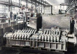
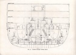
I am currently building a working 1:37 model of the starboard triple expansion steam engine that I found on a 3D-printing website. Click here if you want to see the project in its current state. Since I also have a propeller, I would like to attach it to the engine via a thrust block, but I will have to model the block by myself in CAD. However I can not find any detailed drawings of it. I know that there are 2 sets of 7 axial plain bearings, and I know of one physical model and one free-standing 3D-model but those are missing any sources and I cant take any measurements, and there are pretty big differences between the models, especially the base.

Can anyone give some input into this?
 
Hello,
I've found in my archive a poor picture of RMS Britannic Thrust Blocks at H&W workshop.
Should be quite similar as those on RMS Titanic.

Also attached a cross section drawing of RMS Titanic at Turbine output. On ths drawing you can find also the thrust block on their bases
Enjoy
 

Attachments

  • Britannic_Thrust_Blocks_at_workshop_color.jpg
    Britannic_Thrust_Blocks_at_workshop_color.jpg
    537.5 KB · Views: 44
  • Titanic_Engine_Room_Cross_Section2_Enhanced.jpg
    Titanic_Engine_Room_Cross_Section2_Enhanced.jpg
    576.2 KB · Views: 31
Last edited:
Thank you so much, that really helps, it looks pretty much like the 3D-model on YouTube. Do you have any information on the colour they were painted in? The THG 401 Project has them in white like the rest of the turbine room, while the 3D-model I mentioned has them in light mast like the engine base/collums.
 
Have no idea regarding the right color to be used.

For more informations on these Thrust blocks You can also have a look on the Titanic's Reciprocating Engine Thread created by Cian O'Reilly on ET forum HERE from page 8

Also have a look on this interesting video of the Titanic Triple Expansion engine 65/1 working model equipped with thrust blocs


Back
Top