Vertical Closing Watertight Doors
Titanic's automatic closing watertight doors were all located on Titanic's tank top level, starting at bulkhead D on forward frame 78, 192fti from the stem. The first door was located at the aft end of the fireman's, or pipe, tunnel, after which a small watertight vestibule was created with another watertight door located aft 9ft away. The reasoning for this is explained by Harland and Wolff architect Edward Wilding:
We have a very strong prejudice at Harland & Wolff's to having a watertight door actually adjacent to coal, which has to be worked during the voyage. No. 3 hold was used as a reserve bunker. In order to maintain the intactness of this D bulkhead, which is at the after end, and yet enable coal to be got out of it at sea, a watertight box was built over the after end of the pipe tunnel, having ordinary non-watertight doors opening into the reserve bunkers and having a watertight door on the after side opening into the stoke hole. So that, if necessary, reserve coal, when being worked out with the reserve bunker nearly full, did not come in contact directly with the watertight door.ii
The chart below shows the bulkheads on which the doors were located (letters and numbers), the dimensions of the doorsiii, along with the distance between the aft door and the forward door of each compartmentiv, along with the contents (on the tank top level) of that space. Also shown is the approximate distance of door from midships.v
|
Bulkhead Letter From Forwardvi |
Bulkhead Number From Forward |
Size Height x Width |
Distance From Last WTD Forward |
Content of Space Between Doors On Tank Top Level |
Approximate Distance From Midships to Center of Door |
|
D* |
4 |
5' 6” x 4' 0” |
|
|
|
|
D** |
4 |
5' 6” x 4' 0” |
9' |
Watertight Vestibule |
|
|
E |
5 |
5' 6” x 4' 0” |
54' |
Boiler Room 6 |
9' 2” |
|
F |
6 |
5' 6” x 4' 0” |
58' 6” |
Boiler Room 5 |
9' 2” |
|
G |
7 |
5' 6” x 4' 0” |
57' |
Boiler Room 4 |
9' 2” |
|
H |
8 |
5' 6” x 4' 0” |
63' |
Boiler Room 3 |
9' 2” |
|
J |
9 |
5' 6” x 4' 0” |
58' 6” |
Boiler Room 2 |
9' 2” |
|
K |
10 |
5' 6” x 2' 9” |
24' |
Boiler Room 1 |
8' 6” |
|
L |
11 |
5' 6” x 2' 9” |
69' |
Reciprocating Engines Room |
4' |
|
M |
12 |
5' 6” x 2' 9” |
54' |
Turbine Engine Room |
11' |
|
N |
13 |
5' 6” x 2' 9” |
66' |
Electric Engine Room |
6' 10½” |
|
O |
14 |
5' 6” x 2' 9” |
54' |
Shaft Tunnels |
7' 6½” |
* Located at the end of the Fireman's Tunnel
** Located at the forward end of boiler room 6
As can be seen from the chart above, the doors forward of bulkhead K were bigger than those aft. This was due to the fact that the doors forward of K all corresponded to the boiler rooms in which various equipment and men needed to be able to pass through. These large doors weighed 1,680lbs.vii
Only the doors on bulkhead D were aligned amidships. The rest of the doors were off to the starboard by the distances shown in the previous chart. The watertight doors on bulkheads E–J, and the aft door on bulkhead Dviii, were not aligned with the bulkheads themselves, but instead stepped aft.
The passageway between bulkheads E-J and the doors, much like the vestibule at the end of the fireman's tunnel on bulkhead D, was made watertight and connected to the bulkhead itself. Each passage between E-J was only the height of the watertight doorsix and ended at the forward none watertight bulkhead of the foremost coal bunker of each boiler room, of which also housed the door. The aft door on bulkhead D also ended at the foremost coal bunker of boiler room 6, with the bunker bulkhead also housing its door.
The chart below shows the bulkhead of each door between D and J, along with the approximate distancex they were stepped aft of their respective bulkhead.
|
Bulkhead |
Distance of Door from Bulkhead |
|
D |
9' |
|
E |
9' |
|
F |
10' 6” |
|
G |
10' 6” |
|
H |
13' 6” |
|
J |
12' |
The door design was of Harland and Wolff's own being featured for the first time aboard the Olympic.xi The main draw being that the doors closed by gravity, and thus did not have to rely on any outside force. Harland and Wolff themselves however, did not manufacturer the doorsxii that were, 'a heavy cast iron door' with the door plate being strongly ribbed, that slid 'in a heavy cast iron frame'xiii that was bolted to the bulkhead. Wilding would describe:
In the cast iron frame there is a fairly loose fitting groove which allows the door to slide pretty freely up and down.... On the face of the door, and forming part of the casting, and machined in the fitting shop so as to produce a good fit - the back of the door is also machined to be a good fit - there are a number of tapered wedges. In the door frame are a number of lugs with the under side also machined, forming corresponding wedges tapered the same way, so that when the two wedges come together they will fit. As the door comes down it is quite free until the wedges are opposite their corresponding lugs in the frame, and then the wedges engage and wedge home. There are 6 on each side, 12 in all; they wedge home the machine-backed surface of the door against the machined surface of the frame. Those two machined surfaces, carefully prepared, pressed carefully together, make a very good means of obtaining watertight work.xiv
The doors were held open by two sets of multiple friction disks. One set of disks was connected to the gear shaft of the door. This shaft, held by bearings, was fitted with two worm wheels (pinions), one fitted to a gear rack located in the center of the door, with the other being discussed further on. The other set of friction discs was housed in a clutch kept locked by a weighted bell crank. Weight from the bell crank pressed the disks within the clutch to the disks connected to the shaft, thus creating the friction that kept the doors open. All one needed to do to close the doors was lift the bell crank lever, thus releasing the clutch, and as such the friction, allowing the gear shaft to turn freely by the weight of the door.
The doors could be activated using several methods. The first being a magnetic solenoid controlled by the bridge. To activate, the person on the bridge had to turn the lever located on the navigation bridge, next to the helm, in a half circular motion to turn 'on' an electric connection. This connection would energize the solenoid located near the door, which magnetically would pull up a lever and release the weight of the bell crank, releasing the clutch, thus relieving the pressure on the friction discs. As Wilding would note the magnetic solenoid, “...only needs to lift the weight by a very small amount consequently one can use multiplying gear and not a solenoid strong enough to lift the actual weight employed for the contact...”xv There was no way to independently work the doors from the bridge, therefore if the doors were activated via the bridge, all the doors were released.
Another means of closing the watertight doors was by hand. Next to the aft side of each door between bulkheads D-K and the forward side from L-Oxvi, at a working heightxvii, was a hand lever 'which could hold out the clutch on the screw gear'.xviii The doors could also be lowered from the deck above the watertight bulkheads by, 'a rod going down as nearly vertical as possible to the door. The rod had on its lower end a worm', that terminated no further than needed to operate the door, 'and that was geared into a worm wheel on the door shaft, and the door could be lowered or raised by that means'xix, for as the rod itself was prevented from moving vertically by a bearing, the door had to be lowered or raised by the turning of the worm into the worm wheel. This 'rod', once it reached the bulkhead deck, was covered by a deck plate like those used to operate the horizontal closing watertight doors, and as such worked in the same manner. In all, the doors from bulkhead D-J could be operated from E deck, while those located aft of J, could be operated from D deck. This worm wheel could not be operated locally.xx
There has been confusion as to rather or not the doors could be closed by hand from the deck above them. This confusion stems from a report by Wilding, given to the Wreck Commissioner's committee during the British inquiry which read, “Each of the 'tween deck doors and each of the vertical doors on tank top level could be operated by the ordinary hand gear from the deck above the top of the watertight bulkhead, and from a position almost directly above the door.”xxi [Author's emphasis]
When asked from what deck the doors could be operated by hand Wilding would reply, “From two positions, one down beside the door itself, and the other from the deck above the top of the watertight bulkheads.”xxii He would further state, when questioned whether the hand gear could be operated from the upper deck, that, “It was D deck aft and E deck forward, but not from the bridge.”xxiii He would collaborate this during the Limitation of Liability hearings stating, “They arm controlled from four positions. Electrically, from the bridge, by hand, from the deck at the top of the bulkheads; by hand, adjacent to the doors, and by a float under the floors.”xxiv
Wilding's only mention of watertight doors being operated from the deck above comes from questioning about the lateral closing watertight doors.
20429. In the alleyways, I think, sliding laterally?
- Yes.
20430. Because they could not descend vertically through the next deck?
- Yes.
20431. And actuated by hand either on that deck or on the deck above?
- Quite right.
Though partially true (more of which will be discussed later), this statement is obviously not made in respect to the doors located on the tank top.
It should be noted that the deck above the tank top, between the stem and bulkhead D and between bulkhead M to the end of the ship, was the Orlop deck, which was not a deck proper due to it not being continues, as there was no deck between bulkheads D-M. The forward space (stem to D) was used for cargo, mail, and baggage. The none deck area between bulkheads D-M was the boiler, machine and bunker spaces. The aft section contained mostly refrigerated storage. In all, these spaces would not be idea for having hand gear for the doors, and only the forward door on bulkhead D and those on bulkheads M-O could be accommodated, with the others having to reach all the way to F deck, as G deck, like the Orlop, was partial.
Perhaps the second 'and' in Wilding's report is miss leading, and it should have read, “Each of the 'tween deck doors and each of the vertical doors on tank top level could be operated by the ordinary hand gear from the deck above the top of the watertight bulkhead, from a position almost directly above the door.” Or perhaps it was merely in reference to the lateral doors. So even though the British inquiry report would quote Wilding's report, and take it one step further, writing, “Each of the 'tween deck doors, and each of the vertical doors on the tank top level could be operated by the ordinary hand gear from the deck above the top of the watertight bulkhead, and from a position on the next deck above, almost directly above the door,” Wilding himself makes no mention that this was so, and logistically this would not be allowed.
The third method of closing the doors, as noted above, was by a float. This float was a hollowxxv cylinderxxvi measuring 18 by 12 inches.xxvii It was placed between the floor plates of the tank top and the stokehold plates the crew walked on.xxviii Once water entered a compartment the float, being 'rather lighter than cork in proportion to their size'xxix would begin to rise. Varying by compartment, the float only needed to rise anywhere from 18in and 2ftxxx, before a rod connected to it held out the clutch, thus releasing itxxxi, allowing the door to drop.
Once released the doors would begin to fall under their own weight. As it is falling, and before the wedges pressed the door home, the distance through which there was contact was an inch or so, up until the last inch in which the door was stopped.xxxii To prevent anyone from being hurt from having the doors just drop, one hydraulic cataract cylinder was fitted to the small doors, and two were fitted on the larger doors. The pistons of the cataracts were in contact of the door's upper T bar stiffener, making contact in the center on the small doors, and flanking (one on each side) the center pinion on the large doors. These cataracts controlled the original decent by a none set speed that was solely dependent on the amount of leakage of fluid 'back past the piston in the cylinder'.xxxiii At the last 18in to 2ftxxxiv, there was a bye-pass round the piston which allowed the door to fall freely. The machined wedges on the frame and door then pressed against one another, pushing the machined back of the door against the machined surface of the frame creating a watertight seal. In all, the doors would close within 25 to 30 seconds.xxxv
One means of reopening the doors was by hand, via a crank located next to the aft side of each door from bulkhead D-K and the forward side from L-O.xxxvi Once the doors had been closed from the bridge, they could not be opened locally due to the fact that they operated locally via the clutch, which was put out of service when the doors were activated from the bridge. In order for them to be worked locally the bridge had to turn 'off' the electric current allowing the solenoid to release the bell crank, which would reengage the clutch.xxxvii At this point the doors could be operated independently from one another.xxxviii
Another method of opening the doors was via the worm gear above the bulkhead decks. This gear could be operated independently from the bridge, meaning that even if the bridge had not turned off the solenoid, they could still be operated from this position, as per Board of Trade regulations. However, in order to do so, a key had first to be obtained from an officer.xxxix
Next to the watertight door activation lever on the bridge were instructions which read:
In case of emergency, to close watertight doors on tank top, press bell; push ten seconds to give alarm; then move switch to ‘on’ position and keep it there, Note: Doors cannot, however, be operated mechanically whilst switch is on.xl
There was one alarm bell, mentioned above, located next to each door.xli Once activated from the bridge there was no way to arrest the decent of the door, as the hand gear, as previously mentioned, would be put out of service due to the removal of the clutch.xlii Instead means of escape via ladders from all compartments were fitted allowing access from the tank top to various upper decks.
In figures 1-4 are pictures of two of Olympic's watertight doors. The lettering shows the position of the various parts of the doors mentioned throughout this paper. After the figures is a key to the lettering.xliii
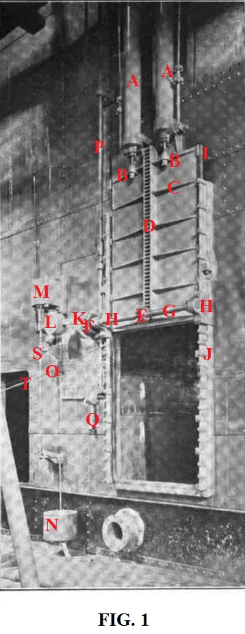
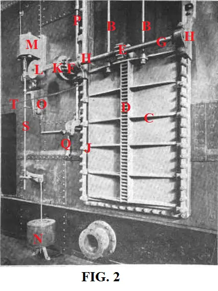
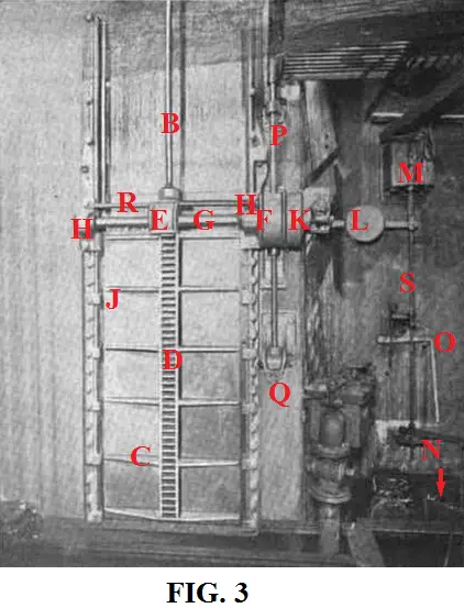

A: Cataracts cylinders.
B: The cataract piston rod connected to T bar (C) of door. Figures 1 & 2 is of a large door used between the boiler roomsxliv, and has two piston rods that are connected to the sides of center pinion (E). Figures 3 & 4, is the a small door located on bulkhead M, having only one piston rod connected to the center.xlv
C: T bar.
D: Gear rack.
E: Center pinion. In figures 3 & 4 this has a cover on it.
F: Main worm wheel (pinion) with friction disks. In figures 3 & 4 this is also covered.
G: Gear shaft.
H: Bearing holding gear shaft.
I: Wedge on door to fit with lug (J) on frame.
J: Lug on frame to fit with wedge (I) on door.
K: Clutch housing.
L: Bell crank.
M: Solenoid to be operated from bridge.
N: Float. In figures 3 & 4 all that can be seen are the levers connected to the float.
O: Hand gear to close door.
P: Rod leading to bulkhead deck to operate door from above.
Q: Hand gear to open door.
R: Unknown upper bar present only in figures 3 & 4.xlvi
S: Rod connecting float, hand gear and solenoid to bell crank (L).
T: Unknown cord/wire, presented only in figures 1 & 2.
Lateral (Horizontal) Closing Watertight Doors
Titanic's 21 lateral closing watertight doors were fitted in various places on decks E, F and Orlop. The doors on E deck were made of wrote steel plate, while the doors on F and Orlop were 'cast iron door plates of heavy section strongly ribbed'.xlvii The farthest of these doors forward was on bulkhead C, while the aft most was on bulkhead O. Not located on the bulkhead itself was the watertight door leading into the Engineer's entrance on E deck, just aft of the reciprocating engine room. Due to the fact that this entrance was on the aft side of bulkhead L, with a passage cut through the bulkhead with a stairway down to the forward side of bulkhead L, it was important that this passage and door be made watertight.
The chart below shows the decks, bulkheads (both letter and number), location of doors from midships, along with the distance to the center of the doors from midshipsxlviii, and their dimensions.xlix
|
Deck |
Bulkhead Letter |
Bulkhead Number From Forward |
Side of Ship From Midships |
Distance From Midships to Center of Door* |
Size of Door Height x Width |
|
E |
K |
10 |
Port |
27' |
6' 6” x 4' 6” |
|
|
K |
10 |
Starboard |
26' 5” |
6' 6” x 3' 0” |
|
|
L |
11 |
Port |
26' |
6' 6” x 4' 6” |
|
|
L |
11 |
Port** |
10' |
5' 0” x 2' 2” |
|
|
L |
11 |
Starboard |
25' 6” |
6' 6” x 3' 0” |
|
|
M |
12 |
Port |
13' 6” |
6' 6” x 4' 6” |
|
|
M |
12 |
Starboard |
21' 9” |
6' 6” x 3' 0” |
|
|
N |
13 |
Port |
12' 9” |
6' 6” x 4' 6” |
|
|
N |
13 |
Starboard |
12' 3” |
6' 6” x 3' 0” |
|
|
O |
14 |
Port |
11' 3” |
6' 6” x 4' 0” |
|
F |
C |
3 |
Port |
12' 5” |
5' 6” x 3' 0” |
|
|
D |
4 |
Port |
12' 5” |
6' 6” x 3' 0” |
|
|
F |
6 |
Starboard |
9' 5” |
6' 6” x 3' 0” |
|
|
F |
6 |
Starboard |
31' 1½” |
6' 0” x 2' 6” |
|
|
H |
8 |
Port |
21' 9” |
6' 6” x 3' 0” |
|
|
H |
8 |
Starboard |
21' 9” |
6' 6” x 3' 0” |
|
|
J |
9 |
Port |
28' |
6' 6” x 3' 0” |
|
|
J |
9 |
Starboard |
28' |
6' 6” x 3' 0” |
|
|
M |
12 |
Port |
12' 1½” |
6' 6” 3' 0” |
|
|
N |
13 |
Port |
12' 3” |
6' 6” x 3' 0” |
|
Orlop |
N |
13 |
Port |
4' |
5' 3” x 3' 0” |
* Italicized numbers are estimates.
** Located at the entrance to the Engineer's passage.
The doors could be closed either locally or from an upper deck. For bulkheads D-J this upper deck was E deck, the deck above the bulkheads. All the doors located on bulkheads K-O were also operated from the deck above their respective bulkheads, which was D deck. The door located on bulkhead C, on F deck, was also operated from D deck, or one deck higher than its' bulkhead deck.l
Next to each door locally was a large open-ended wrench on a clip readily accessible.li This wrench, or spanner, was to operate a nut located on the spindle directly above the bottom pinion. As the spindle itself was connected to the pinions, when the nut was rotated the spindle was rotated, which in turn, rotated the pinion. The gears for operating the doors from an upper deck were marked by a deck plate.
The doors themselves were fitted to a cast-iron frame that was bolted to the bulkhead. The frame itself had fitting strips cast to it, which projecting out, could be chipped by hand, due to their narrowness, to fit or conform, over or to, any irregularities of the bulkheads. These fitting-strips were generally cut away between the bolts to save weight and materiel. These doors operated on a rack (usually made of steel and located on the back side of the door) and pinion (usually made of gun metal) system. The doors were moved across grooves at the top and bottom, having a taper of 3/16 of an inch to a foot. These grooves were made of flat wrought-iron and were secured by the same bolts as the frame, however, these could be taken off for upkeep without disturbing the frame itself. A space was generally left below the lower groove to allow debris to fall clear when operating the doors in order that the door not be blocked or prevented from closing. To prevent the door from jarring when opened, being that the thin part of its edge is in the wide part of the groove, a small parallel groove was at the bottom of each tapered one.
To reduce friction and help with the weight, the doors were supported by two rollers. These were located along the bottom on the same side as the rack and pinion. The forward wheel had connected to it a 1/8in steel plate that prevented it from rubbing against the sill plate, which will be discussed shortly. These wheels were given their own groove or track to work, which tapered with the door's groove.
Riveted along the outer edge of the door, where it made contact with the frame when closing, were perfectly machined parallel strips of brass or gun metal, which formed a perfect watertight seal when fitted with the face of the frame that was also perfectly machined to guarantee an accurate fit. Tapered pieces of similar strips were provided to the opposite surface of the door, which made contact with face pieces, or clips, on the frame performing a wedge action. When closed, due to the fact that the back end of the door had no groove, the projection of the racks were increased locally on the upper and lower door clip so that the pinions pressed against the door, thus the door was held by the shaft pressing against the door frame. There were other clips along the back end of the door as well, that jammed against the back of the bulkhead frame. Also provided were wedges at the end of the guide to prevent the passage of water.
The bottom groove, when the door was opened, was protected by a sill plate, which prevented dirt or other debris from collecting inside. These plates were no thinner that 3/16 of an inch. This sill plate was fitted to open out automatically when closing the door, which was accomplished by a spindle feather which was allowed play within the bottom pinion, so that before the pinion operates movement to the rack when closing, a cam, keyed onto the bottom of the shaft, engaged the stop on the sill and lifted it clear. The sill plate itself was built as a fulcrum with counter weights on its opposite end, so that they would swing back into position when door was reopened.
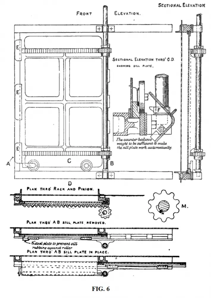
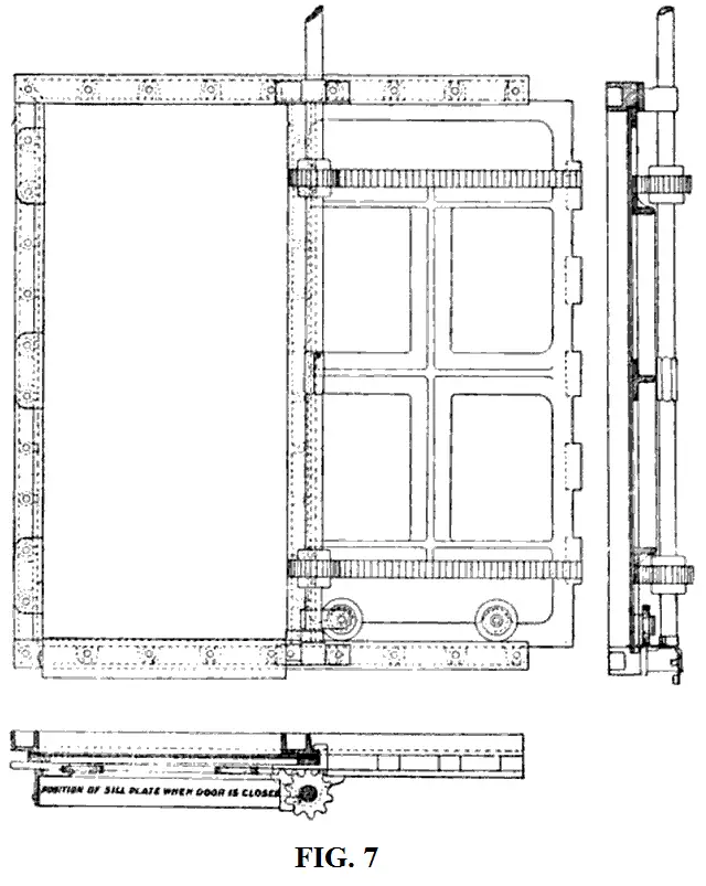
Below is a serious of diagrams of lateral closing watertight doors. In figure 6, the spindle feather is seen (N) in the pinion (M), that operated the cam (F), which is also labeled B in figure 5. In the 'vertical section' view of figure 8, the nut to operate the door, via the large open-ended wrench (spanner) is labeled. Figure 7 is the only diagram of an opened door. Note that the rack is extend onto the upper and lower clip on the right edge of the door (these clips are labeled in figures 5 & 8), thus allowing 'the shaft to press against the frame', when closed.


Deck Plate
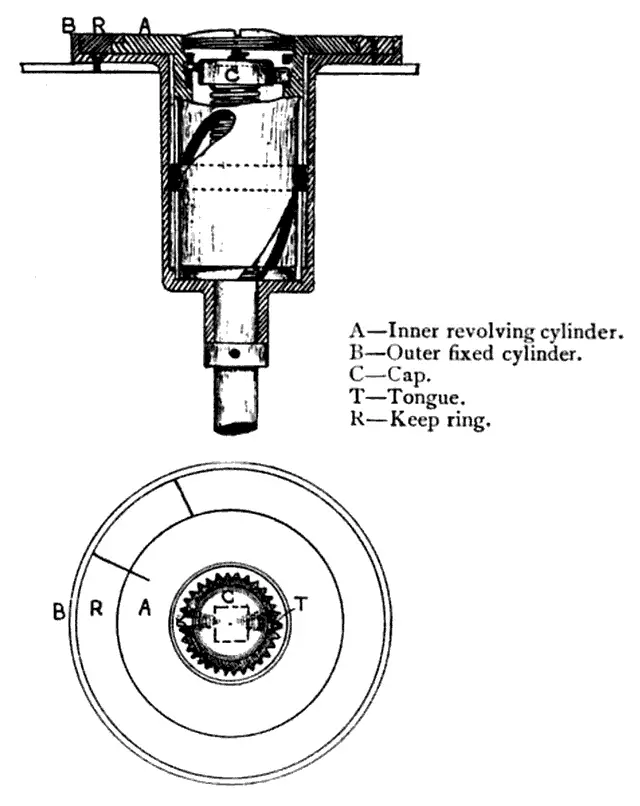
The deck plate was a round brass plate 10in to 12inlii in diameter, that laid flush with the deck. This deck plate consisted of four brass rings. Initialed on the second ring from the outside, was WTDliii (watertight door). Some plates of Titanic's era had the words 'open' and 'shut' or other symbols or letters pertaining to such; sometimes there was merely a line that when closed was completed. Some even had respected arrows pointing in the direction in which to turn the gears. There was also an indicator on the third inner ring that marked rather the door was turned open or shut. However, on merchant ships of the time, these words and/or symbols were sometimes omitted.liv
For quickness, brass signs reading 'WT Door Deck Plate'lv, were posted in alleyways, on pillars or other convenient areas, with arrows to show their location.lvi These deck plates consisted of an outer and inner cylinder, with the outer being secured to the deck, with the inner being able to rotate. To operate, one first needed to remove the cover plate (the inner most ring) with a two-forked pin-spannerlvii or a key.lviii Once opened, the end of the door's spindle (or rod), which raised through the deck, would be visible as a squared or hexed end. Next to the deck plates was a 30in T-handle or box spanner (wrench)lix, with the proper shape to fit over the end of the spindle. If the spindle could not rise to a location suitable for operation, or if more than one location was desired, rods and gears were connected so that it could extend to such locations.lx
As the spindle is twisted an inner nut, which is itself prevented from revolving by side lugs fitted to vertical grooves cut into the outer cylinder, moves up and down and rotates the inner cylinder by the nut passing through the spiral grooves cut within. The rotation of the inner cylinder in turn, points the indicator (if one is present) as to whether or not the door is open or shut. Closing was always done by turning in a right-handed, or clockwise, motion. Over time the gears could become worn causing the indicator to point to the word 'shut', though this had not been properly done all the way; therefore it was most desirable to turn until one could no longer do so.


Sources
A Text Book of Naval Architecture For The Use Of Officers Of The Royal Navy; J.J. Welch; 1891 (pgs. 119-120)
The Code of Federal Regulations of the United States of America; 1966 (pg. 278)
Limitation of Liability Hearings
Marine Engineering; A. E. Tomkins; 1908 (pgs. 584-587)
The Marine Steam Engine 7th Edition; Richard Sennett and Henry John Oram; 1904 (pgs. 367-396)
The Marine Steam Engine 11th Edition; Richard Sennett and Henry John Oram; 1918 (pgs. 364-368)
National Archives: Document MT9-920-A-1 (pgs. 148-152) and MT9-920-C (Which includes Francis Carruthers' report to the Wreck Commissioner of the design and construction of Titanic pgs. 407-08)
Practical Shipbuilding Vol. 1; A. Campbell Holms; 1918 (pgs. 395-397)
Seamanship; Commander Wilfred Henerson; 1907 (pgs. 38-39)
Shipyard Practice as Applied to Warship Construction; Neil J. McDermald; 1911 (pg. 137)
Thomas Andrews' Notebook; Reproduced by Lagan Boat Company N.I. Ltd.
Titanic The Ship Magnificent Vol. 1: Design and Construction; Bruce Beveridge, Scott Andrews, Steve Hall, Daniel Kilstorner and Art Braunschweiger; History Press 2016 (pgs. 110-135)
United States Senate Inquiry into the Titanic Disaster
War-ships; Edward Lewis Attwood; 1904 (pgs. 66-70)
Wreck Commissioner's Inquiry into the Loss of the SS Titanic
Sources Of Figures
Figure 1: Engineering Magazine Vol. 41
Figure 2 & 3: Marine Review Vol. 42
Figure 4: Google search
Figure 5: Marine Engineering
Figure 6: The Marine Steam Engine (1918)
Figure 7: The Marine Steam Engine (1904)
Figure 8: War-ships
Figures of Door Plate (In order): Marine Engineering, Seamanship, Shipyard Practice
Appendix
The Location of Titanic's Automatic Watertight Door Operational Mechanisms
It has been long believed that the operational mechanisms that worked Titanic’s automatic watertight doors were located on the forward side of the door. These mechanisms include, but not limited to, the gears for lowering and lifting the door, the float that tripped the door into closing as the water rose, and the cataract cylinders that regulated the initial speed in which the doors dropped. These doors were all located along Titanic’s tank top deck corresponding to Titanic’s watertight bulkheads. They were of two sizes, with the doors from bulkhead D (both the fore and aft door on this bulkhead) to bulkhead J (there was no I) having the large doors measuring 5’6” tall and 4’ wide. All these doors led to the boiler rooms, and as such, were wider to allow various crew members and equipment ease of access. The larger doors also had two cataract cylinders attached to them. The smaller doors were located from bulkheads K-O, and corresponded to the three engine rooms and the shaft tunnel. These doors had only one cataract cylinder attached.
The belief that the mechanisms for the doors were located on the forward side is supported by the testimony of Titanic survivor Frederick Scott, who was located in the turbine engine room when Titanic collided with the iceberg. After the impact Scott would witness the watertight doors closing, which would prompt him and a mate to go aft and open the watertight door on bulkhead O by two feet allowing a fellow crew member escape from the shaft tunnel. Scott would then return to the turbine engine room. He would tell his inquires, during the British investigation, what happened next:
5584. Then when you got there did you get further orders about the watertight doors?
- Yes, the engineer of the watch in the engine room.
5585. What did he tell you to do?
- He told us to heave all the watertight doors up.
5586. Did you go right aft again to the aftermost tunnel?
- Yes, we went right through. We opened one up in the afterside of the turbine room, and then went right through them till we got to the after one, which we had opened up about two feet.
5587. Now, let us see if I follow. In order to get to the aftermost tunnel you would again have to go up the escape?
- If we had not opened the doors we would have to go up the escape; but as we went through we opened them up.
5588. I thought you went up the escape and then opened them coming forward?
- No.
5589. Did you open them going aft?
- You are bound to, because the handle is this side of the door.
5590. The handle is this side of the door?
- Yes; and then we passed through and opened up another.
5591. You would pass first of all from the turbine engine room?
- Into the electric engine room.
5592. And you go into the electric engine room. When you say you opened them, how much did you open them?
- Right up.
5593. Can you give us an idea how much that is?
- Just over 6 feet, I think. I could walk through them easy without bending down.
The belief in the location of the mechanisms is furthered by testimony given by Harland and Wolff architect Edward Wilding, who was summoned as a technical expert during the British inquiry.
20445. I think your model is sufficient. In the first place, you have spoken of the descending door. Supposing that water was gaining access into the compartment on one side of the door in volume, so that there was water flowing along rapidly, would that stop the door descending?
- It would not; we have had proof that it would not.
20446. You have had proof?
- Quite.
20447. In what way?
- In the case of the "Olympic" accident. A stoker was standing by the door in O bulkhead in the tunnel in the aftermost section of the tunnel, forward of the propeller here. (Pointing on the model.) It was put in evidence at the "Olympic" trial, and can be turned up therefore, that he saw the ram come through, and as the ship drifted out he saw the water come in with a rush; the automatic release from the bridge had not yet been worked, and he took the hand lever, standing on the fore side of the door, [author's emphasis] and released that door, and it fell and closed properly, but during the time it took to do so sufficient water had come through the door to bring about 3 feet of water into the next forward section of the tunnel - some 300 or 400 tons of water had come through. The door closed, and the water was pumped out; so that it closed against the rush of water.
In support of both men's testimonies is photographic evidence (figure 1) of the watertight door on Olympic's bulkhead M. This door separated the turbine engine room from the electric engine room. Figure 2 is a plan of both the Olympic's and Titanic's electric engine room, with a red circle around the area featured in figure 1, and a red arrow showing the area in which the door's mechanisms were. Note how in figure 2 the bulkhead dips aft, something that is not immediately noticeable in Figure 1 at first glance.


This photographic evidence shows us that indeed the mechanisms for operating this watertight door was on its forward side. This along with the testimonies of both Scott and Wilding leaves little question that the doors from bulkheads M-O were mounted and operated from such position. But what about the doors from bulkhead D-L?
Greaser Thomas Dillon was working in Titanic's reciprocating engine room when the collision occurred and the watertight doors closed. Like Scott he would hear the order to open the watertight doors back up. His testimony reads:
3738. What order
- The next order we got was to get out of the engine room and into the stokehold and open the doors.
3739. Open what doors?
- The watertight doors or watertight compartments.
3740. Was that possible; could you do it?
- We assisted to do it.
3741. As I understand it the watertight doors had been closed from the bridge?
- Yes.
3742. Could you open them from below?
- One leading from the engine room to the stokehold was lifted up high enough by hand to let us get underneath.
3743. You could open them by hand?
- Yes, by a pump.
3744. (The Commissioner.) By a pump; what is the meaning of that?
- The pump wheel.
3745. (Mr. Raymond Asquith.) Did you open the watertight doors?
- Yes, I assisted to open them as far as we could forward.
...
3804. (The Commissioner.) That is so, is it? You could only open them with the concurrence of the people on the bridge?
- We opened them by hand.
...
3959. But how many of you went? First of all you went from the engine room to No. 1 boiler room?
- Yes.
3960. You went through a watertight door for that purpose?
- Yes.
3961. How many of you went through that watertight door when you did?
- About six or seven - seven.
3962. How many of you helped to open the watertight door?
- As we got into each section the men were in it, in their own boiler rooms. At No. 1 boiler room we had to lift the door up, and when we got to the next section there were men belonging to that section in it.
3963. You lifted No. 1; how many of you did it?
- Three - three on the pump.
3964. What did you do it with? How did you do it?
- With a pump handle.
3965. You turned that?
- Yes.
3966. Was it two or three turned that handle?
- Two or three.
Dillon would also speak to the press, telling the Daily Mail, which would subsequently be repeated in the June 27, 1912 'The Herald', that:
The after engine-room door was lifted up half way, enough for us to crawl under. All the water-tight doors were opened by us with the handle, but the chief engineer told us not to touch No. 5 door as that was finished.
From this article and Dillon's testimony, we can see that he worked his way from aft to forward, going from bulkhead K-G. Both of his accounts clearly makes it sound as if the hand gear, or pump- as he called it, was on the aft side of the door, taking two to three men to operate. This evidence is against what we have established so far, so is there any proof of Dillon's claims? In fact there is, but first let us examine the relationship between Titanic's watertight doors and boiler rooms.
From the aft door on bulkhead D to the door on bulkhead J, the doors were not flushed with the bulkheads, but instead were stepped aft. Due to this stepping, a tunnel was created from one boiler room to the next, except in the case of the aft door on bulkhead D which was aft of a watertight vestibule. The height of the tunnels for bulkheads E-J is explained by Wilding in question 20676 of the British inquiry, “..the passage, the trunk passage from the bulkhead to the watertight door, is only just the height of the watertight door.” Figure 3 shows this 'trunk passage', or tunnel, and the relation of the watertight bulkheads (red arrows) and the doors (red circles). It should be noted that the doors were kept on the forward coal bunker bulkhead of each boiler room. The coal bunker bulkheads themselves were not watertight, thus the need for the watertight bulkhead to be extended to the door.

The next figure is a three dimensional mock-up of the tunnel area between boiler room 5 and 4. Though not to scale, nor in accuracy in the placement of the tunnel, it does give the reader a better understanding of how the tunnel went from the aft coal bunker bulkhead (purple) of the forward boiler room (5), through the coal bunker spaces (green), with the watertight bulkhead (red) between the forward and aft bunkers, and how the tunnel exited through the forward coal bunker bulkhead (blue) of the after boiler room (4).

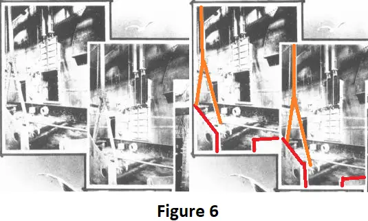
Now we will look at a couple of photographs (Figure 5) taken of another one of Olympic's watertight doors.

A couple of things are immediately noticeable. First the door has two cataract cylinders, which means that the door belongs to any bulkhead from D-J. The second is that the door is not located within a tunnel, as one would expect it to be if the door's mechanisms were located on its forward side. In fact, it appears in the first photograph with the door opened, that the door is leading into a tunnel. This rules out the aft door on bulkhead D, as that door led into a watertight vestibule and not a tunnel. The last thing to note is the head room needed to house the cataract cylinders and the door. Such head room would not have been available from inside a tunnel, in which the photo is clearly not taken in.
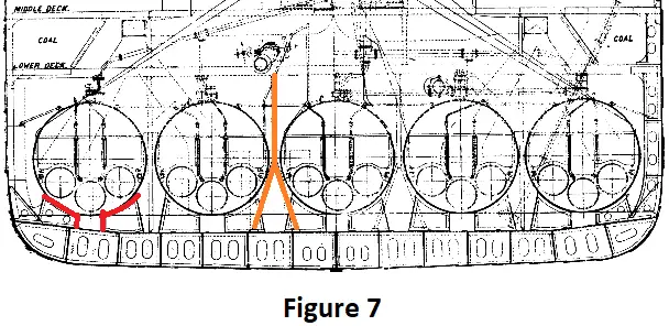
The next figure (6) is of the same pictures in figure 5, just from further out. The pictures in figure 6 are doubled, with some distinguishable features highlighted. These features allow us to place the photos in respect to a schematic (figure 7) of one of Titanic’s boiler rooms. Note in figure 7 how the inverted Y sanction is only present on both sides of the center boiler. It is unclear if such a sanction was used in boiler room 6, as this room only had only 4 boilers and not 5. This sanction would roughly sit right behind the watertight door. Due to the fact that there are boiler seats (red) present in figure 6, and the Y sanction, the door pictured could not be the forward door on bulkhead D which led from the fireman's tunnel into the watertight vestibule, in which no boilers were located.
This photographic evidence along with the testimony given by Dillon, leads to the conclusion that the doors from bulkhead E through K were operated by mechanisms located on their aft side. As far as the doors on bulkhead D, we can come to a reasonable conclusion that the forward door, leading to the fireman’s tunnel, most likely did not have the head room within the tunnel itself to house the cylinders nor the doors, therefore it is more likely than not that this door also operated from its aft side. If there was any uniformity, than the aft D bulkhead door would also have been operated from its aft side- inside boiler room 6. That being said, it is plausible then that the door on bulkhead L was operated from its forward side like the other engine room doors.
i MT9-920-A-1 (pg. 162)
iiWilding Limitation of Liability hearings (abbreviated L&L from here on out) May 13
iii MT9-920-A-1
iv Not to be confused with the distance between bulkheads.
v Based on original Harland and Wolff bulkhead plans reproduced by Bruce Beveridge, Titanic the Ship Magnificent Vol. 1; pgs. 125-134.
vi There was no bulkhead I.
vii 20440
viii The aft door leading into boiler room 6.
ix 20676
x Based on the ship's plans by Bruce Beveridge at https://www.encyclopedia-titanica.org/titanic-deckplans/tank-top.html
xi Wilding L&L May 13
xii Wilding L&L May 14
xiii Wilding L&L May 13
xiv 20435
xv 20450
xvi See Appendix
xvii 20450
xviii MT9-920-C
xix 21124
xx Wilding L&L May 14
xxi 21127-21128A
xxii 21126
xxiii 21127
xxiv Wilding L&L May 13
xxv 20665
xxvi Usually made of copper.
Reports of Patent, Design, and Trade Mark Cases Vols. 25-26 1908, pg. 1903
The Engineer Vol. 96, 1903 pg. 546
The Week's Progress Vol. 22, 1903 pg. 500
xxvii 20451
xxviii The crew did not walk directly on the tank top floor plating due to piping and other obstacles.
xxix 20456
xxx 20454
xxxi 20453
xxxii 20439
It was not uncommon for vertical doors of Titanic's era to be tapered 3/16 of an inch per foot run, with their frames also being tapered such. Also common was the fitting of brass strips, or like material, around the edges of the door where it came into contact with the frame in order to secure a watertight fit. However, there is no evidence that any of these was the case for any of the Olympic class vessels.
xxxiii 20442
xxxiv 20442 As one may have noticed, these are the same figures given for how high the float needed to rise.
xxxv 21127
xxxvi See Appendix
xxxvii Wilding L&L May 14
xxxviii It has been stated that once a door was re-opened the float would no longer be engaged, and as such would not re-close the door due to flooding. This was not the case. Once the bridge deactivated the solenoid, the clutch, in which the float was connected, was reengaged with no reason for the float to be disconnected. Video of at least one door on Titanic's wreck shows it closed, when evidence clearly states that it was reopened, though it is unclear whether this door was re-closed by hand or by the float.
xxxix Wilding L&L May 14
xl 3976
xli Thomas Andrews Notebook; Reproduced by Lagan Boat Company N.I. Ltd.; Pg. 30
xlii On the Stone Lloyd hydraulic doors, one could hold the door from closing by holding a handle, thus allowing escape. Once the handle was let go of the door would begin to close again. Though some publications of Titanic's time says the same for the Olympic class vessels, and as such has been repeated in modern text, there is no evidence that this was the case, nor would the mechanical means allow for such.
xliii A 1913 patent, later published on June 30, 1914, by William Edward Armstrong, for a new and useful improvements in apparatus for working the watertight doors designed by Harland & Wolff, is located at the following website.
xliv This author speculates, but has no definitive evidence, that this door may be the one for bulkhead J, though further research will be needed before this claim, if true, can be substantiated. Thus, this hypothesis should not be read by any means as being factual, and is presented here in case future research shows it to be true.
xlv How this was connected to the center without interfering with the center pinion is unknown, as of now, to this author.
xlvi Thanks to Ralph Currell, who pointed out to this author that perhaps this bar was to merely hold the gear cover, as present in figures 3 & 4.
xlvii 21127
xlviii Based on the bulkhead plans reproduced by Bruce Beveridge based on original Harland and Wolff plans: Titanic the Ship Magnificent Vol. 1; pgs. 122-134.
xlix MT9-920-A-1
l MT9-920-C
li 6302-03
Such wrench can be seen in a picture of Olympic's lateral closing watertight door, on page 117 (figure 6-11) of 'Titanic the Ship Magnificent Vol. 1'. First class passenger George Harder would describe crew members holding 'Stilson' wrenchs (an adjustable wrench, usually for rounded surfaces, that tightens with pressure) or 'something like that' (US Inquiry) when operating the watertight doors. Though not a hundred percent clear, these may have been the large open-ended wrench described. Third Class Steward John Hart would recall closing the E deck doors via a large spanner, though no direct description is given. (10312)
lii George Harder US Inquiry
liii George Harder US Inquiry
liv There is no testimony of Titanic's deck plates saying or indicating anything else but 'WTD'.
lv It is unclear as to how the deck plates were distinguished from being for the vertical doors or for the horizontal doors, except perhaps that one needed a key to operate the vertical door deck plates.
lvi Wilding's report to the Wreck Commissioner would read, “To facilitate the quick closing of the doors from deck, plates were affixed in suitable positions on the sides of the alleyways indicating positions of the deck plates.” Though only mentioning the alleyways, photographic evidence also shows at least one sign on the side of a column in the second class dining saloon on D deck. (Titanic the Ship Magnificent Vol. 1; pg. 118 Fig. 6-14)
lvii Norman Chambers US Inquiry
lviii Wilding L&L May 14
As was the case for the vertical doors located on the tank top. It is unclear whether a two-forked pin-spanner might still be needed.
lix Norman Chambers US inquiry and 21128
Also referred to as a socket spanner in some texts.
lx This may indeed have been the case for some of Titanic's doors as passenger Norman Chambers would recall that the deck plates opened to a 'double series of bevel gears, the last shaft having on it a pinion meshing in a door rack and closing the door.” (US Inquiry) Had the spindle (rod, shaft) just reached to the bulkhead deck directly, there would be no reason for having a 'series' of gears underneath the deck plate.

Comment and discuss