TimTurner
Member
I'm building a computer model of titanic and I'm trying to understand the layout of the upper boiler rooms and coal bunkers. I'm working off of the Bruce Beveridge schematic and some of the geometry is less clear here.
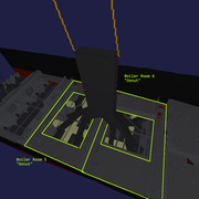
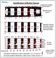
1. Above the boiler rooms, the room narrows, like a big square donut with the smoke risers coming up through the middle. The area around that seems to be part of the coal bunker - sort of. But how is the weight of that coal supported? How do the trimmers move the coal out of that big flat area down to the vertical sections where it can fall down to deckplate level? Is this really part of the coal bunker?
2. What's on the sides of the donuts - the part that isn't over the vertical coal bunker? There are these large flat planes port and starboard hanging over the boiler room. There's no obvious way for coal here to fall into the verticals.
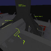
3. The Bruce Beveridge schematic has these large rectangles in parts of the "donut" floor. I've been interpreting them as holes for the coal to fall through into the verticals of the coal bunkers, but there are smaller holes elsewhere with clear support beams. These holes seem oddly placed to let a substantial amount of coal fall from above, especially in the flat places near the hull towards the center of the boiler rooms. I've highlighted one of the "hole" rectangles below with the arrow.
Color Code:
Black = hull (above anti-fouling paint)
Red = Hull (Anti-fouling paint - below waterline)
Gray = Deck and interior bulkhead
Dark Gray = Boilers, Smoke risers
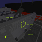
Tan = Steam piping
Yellow = Funnel
1. Above the boiler rooms, the room narrows, like a big square donut with the smoke risers coming up through the middle. The area around that seems to be part of the coal bunker - sort of. But how is the weight of that coal supported? How do the trimmers move the coal out of that big flat area down to the vertical sections where it can fall down to deckplate level? Is this really part of the coal bunker?
2. What's on the sides of the donuts - the part that isn't over the vertical coal bunker? There are these large flat planes port and starboard hanging over the boiler room. There's no obvious way for coal here to fall into the verticals.
3. The Bruce Beveridge schematic has these large rectangles in parts of the "donut" floor. I've been interpreting them as holes for the coal to fall through into the verticals of the coal bunkers, but there are smaller holes elsewhere with clear support beams. These holes seem oddly placed to let a substantial amount of coal fall from above, especially in the flat places near the hull towards the center of the boiler rooms. I've highlighted one of the "hole" rectangles below with the arrow.
Color Code:
Black = hull (above anti-fouling paint)
Red = Hull (Anti-fouling paint - below waterline)
Gray = Deck and interior bulkhead
Dark Gray = Boilers, Smoke risers
Tan = Steam piping
Yellow = Funnel