Hi All, This is my latest project...I'm working on the Titanic main Engines - these images show the latest progress...
44865
 

Attachments

  • screenshot012.png
    screenshot012.png
    1.2 MB · Views: 2,232
  • screenshot013.png
    screenshot013.png
    882.8 KB · Views: 1,841
  • screenshot014.png
    screenshot014.png
    816.7 KB · Views: 3,296
  • screenshot015.png
    screenshot015.png
    854.4 KB · Views: 6,136
  • screenshot016.png
    screenshot016.png
    1.2 MB · Views: 1,423
Hi Cian,
I don't know if you have the original copy of the blue print drawings for the engines. If so can you tell me how many pieces the crankshaft was from?
 
Hi Mike, For the most part (so far) the model is based on the Britannic's engines. I used reasonably good plans found here - Plans - as reference along with photo's and a fair chunk of advice from various experts on other forums (Facebook has a load of groups for Titanic modellers). HOWEVER!!!! While the plans linked here are pretty good, the Britannics engines were not Identical, The Titanic/Olympic's Low Pressure Cylinder is quite different in structure to Britannics. Broadly speaking though they are an good match.
 
Hi Cian, I am guessing you have machine shop experience behind you.
I am interested how a large crankshafts where made in those days. Looking at a photo in The Ship Magnificent book show only one section of the Olympic crankshaft in a lathe. That to looks like has been made up of five pieces. As to-day crankshafts are usually made from a one piece casting or forging. Have you managed to find some of the original blue print machine shop drawings?
 
Hello Mike.

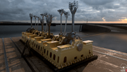
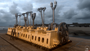
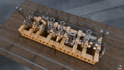
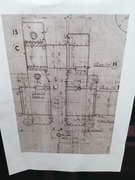
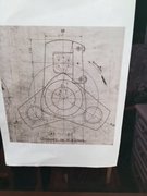
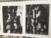
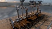
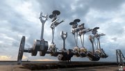
I once worked for a Dutch, Engine manufacturing Company Named Smit-Bolness. Their crankshafts were built. This enabled construction of the engine as a series of "G" Frames Thus it was easy to add or subtract a cylinder and the crankshaft components were a "one size fits all". Not only that, they could run on almost any kind of diesel... even crude itself.
Any of you our there from Liverpool who are old enough, will remember the suction dredger "WD Mersey". She was equipped with three such engines...totally amazing!
 
I have been to the Kempton steam museum to see how the crankshaft was assembled on their 800 ton triple expansion engine built in 1926.
Each conrod pin shaft and crankshaft is a shrink fit bores into a web shape plate with a 2'"3/4 dia pin to prevent any turning movement. The centre crankshaft conrod pin bearing is made removable from the web shape plate as the crankshaft is made up of two section and is delivery that way due to the railway weight limit of 16 tons. The crankshaft is really fabricated from shafts and plates made from 13 pieces for three cylinder engine. If Titanic crankshaft was built in the same way for a four cylinder engine 17 pieces.
Do we known if the engines were ever steam up in the workshop before been placed in the ship?
 

Attachments

  • Kempton crankshaft & con rod..JPG
    Kempton crankshaft & con rod..JPG
    15.4 KB · Views: 947
  • Kempton crankshaft.JPG
    Kempton crankshaft.JPG
    13.7 KB · Views: 883
Hi Cian,
Please lets us know the progress of your engine. Can you give the size of your engine. Like the diameter of the crank bearing and is a one piece. Do you plan to run it on steam?
 
Re looking at further photos of Britannic crankshaft. It would appear is made up from 20 pieces with a further 16 dowel pins to prevent shafts and rod pins journals turning out of position. Plus a further nuts and bolts used for joining the crankshaft into a one piece. To achieve correct alignment and straightness was no mean achievement and amazing what they could do in those days without electronics and computers aids.
As for shrink fit shafts and rod pins does any body know if heat or liquid nitrogen freeze fit was used?
 

Attachments

  • 433 Britannic Crankshaft.JPG
    433 Britannic Crankshaft.JPG
    24.6 KB · Views: 908
  • Britannic Crankshaft on lathe.JPG
    Britannic Crankshaft on lathe.JPG
    28.4 KB · Views: 779
Hi Mike, these images should give you a clearer idea of the crankshaft configuration. At the moment I haven't yet built the Piston rods for the main cylinders, though as you can see the Connecting Rods are there. Regarding positioning the cranks (and therefore the rods/Pistons) I haven't set the correct angles yet. The valve gear/stephonsons Links are set in the 'neutral position' indicating the engine is stopped.
screenshot000.jpg
screenshot000.png
screenshot001.jpg
screenshot002.jpg
 

Attachments

  • screenshot003.jpg
    screenshot003.jpg
    563.4 KB · Views: 1,159
  • screenshot004.jpg
    screenshot004.jpg
    377.8 KB · Views: 885
  • screenshot005.jpg
    screenshot005.jpg
    653.3 KB · Views: 1,390
  • screenshot006.jpg
    screenshot006.jpg
    597.4 KB · Views: 1,153
  • screenshot007.jpg
    screenshot007.jpg
    547.4 KB · Views: 1,134
Your crankshaft is looking great work. Can you please give me the scale size as to Titanic size.
How many pieces is the crank made up from?
I am intrigue where the background is?
 
Back
Top