Titanic's Reciprocating Engines

Hi, there

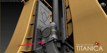
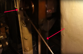
A question about the telescopic device attached on top of each connection rod (see attached picture)

What's the purpose of this device?

In some posts on this forum, it was mentioned as being surely a kind of telescopic pump used for lubrication of the crosshead pin.

But I don't thing so.

My understanding is that device is used for indicating the steam engine when setting adjustments have to be applied on the reverse gears or for other performance tests of the engine.

The end motion of the telescopic link close to the Y frame, is replicating, at a smaller scale, the true displacement of the piston during his stroke.

And during indicating measurements, each ends of these telescopic links are connected by mean of a cord to one indicating device installed close to each cylinder.

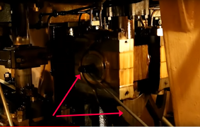
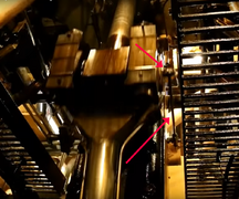
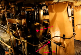
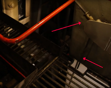
On the second here attached picture, we can see an another equivalent telescopic device used on SS Jeremiah, specialy made and added during indicating this triple expansion steam engine.

Link to the video from wich this picture was extracted is HERE

Is my analysis correct?
 

Attachments

  • Britannic_Engine_Shop_Assy_Telescopic_device_on_Connecting_Rod.jpg
    Britannic_Engine_Shop_Assy_Telescopic_device_on_Connecting_Rod.jpg
    131.7 KB · Views: 158
  • Indicating_Steam_Engine_SS_Jeremiah.jpg
    Indicating_Steam_Engine_SS_Jeremiah.jpg
    226.2 KB · Views: 152
Hello Jim,

Thanks for yor answer.

That's what I thought also at first sight, and what also seen on few other 3D modeling of this engine, as the one here attached.

Now, I've some doubt on those device.

It seams that each cylinder has two telescopic devices attached to the side of their connecting rod pins

This connection is made on a thin bracket bolted to the side and under of the connecting rod pin witch can't be, from my point of view, used to pass oil in thru and lubricate the pin brasses.

I've attached a detail of this connection from a 3D drawing made here by Cian O' Relly for a better understanding.

It should be more simple to connect a swivel joint directly in the center of the connecting rod pin if intention was to lubricate this part with such kind of device.

And the triangular bit at the end of the telescopic device, close to the Y frame is very small for me and can't be an oil cup if the telescopic device is expected to be an oil pump.

From my point of view it may be something different.

The picture I've attached in my previous conversation is related to the Britannic engines and was taken during shop ass'y.

But the assembly where not fully finalized when the picture was taken, and so may be some others part connected to the end of theses devices where not still in place.

I've seen on several videos made on SS Jeremiah O'Brian and as well on SS John W. Brown, very similar devices installed. Both are Liberty Ships

They are on those vessels installed also on each Y frame and attached to the connecting rod pin of each cylinder, but are used as simple mechanical actuator to drive other oil lubricators

And these oil lubricators seams to be dedicated to cylinder and valves lubrication.

Lubrication of their connecting rod pin brasses are made by gravity by means of oil cups attached to them.

Here attached some anotated pictures from SS Jeremiah O'Brian and SS John W. Brown

What do thing about this proposal ?
 

Attachments

  • Titanic_Engine_Room_360_Oil cup feeding Telescopic_Device.jpg
    Titanic_Engine_Room_360_Oil cup feeding Telescopic_Device.jpg
    154.5 KB · Views: 135
  • Connecting rod pin_Connection for telescopic_device.jpg
    Connecting rod pin_Connection for telescopic_device.jpg
    291.7 KB · Views: 118
  • Connecting_Rod_pin_Forced_Lubrication_SS_Jeremiah_O'Brian_1.jpg
    Connecting_Rod_pin_Forced_Lubrication_SS_Jeremiah_O'Brian_1.jpg
    236.9 KB · Views: 124
  • Connecting_Rod_pin_Forced_Lubrication_SS_Jeremiah_O'Brian_2.jpg
    Connecting_Rod_pin_Forced_Lubrication_SS_Jeremiah_O'Brian_2.jpg
    261.8 KB · Views: 122
  • Connecting_Rod_pin_Forced_Lubrication_SS_Jeremiah_O'Brian_3.jpg
    Connecting_Rod_pin_Forced_Lubrication_SS_Jeremiah_O'Brian_3.jpg
    312 KB · Views: 129
  • Connecting_Rod_pin_Forced_Lubrication_SS_Jeremiah_O'Brian_4.jpg
    Connecting_Rod_pin_Forced_Lubrication_SS_Jeremiah_O'Brian_4.jpg
    368.4 KB · Views: 126
  • Connecting_Rod_pin_Forced_Lubrication_SS_Jeremiah_O'Brian_7.jpg
    Connecting_Rod_pin_Forced_Lubrication_SS_Jeremiah_O'Brian_7.jpg
    217.5 KB · Views: 112
  • Connecting_Rod_pin_Forced_Lubrication_SS_Jeremiah_O'Brian_8.jpg
    Connecting_Rod_pin_Forced_Lubrication_SS_Jeremiah_O'Brian_8.jpg
    115.4 KB · Views: 108
  • Oil_Lubrificator_actuated_by_alternative motion of connecting rod pin_SS_Jeremiah_O'brian_2.jpg
    Oil_Lubrificator_actuated_by_alternative motion of connecting rod pin_SS_Jeremiah_O'brian_2.jpg
    156.4 KB · Views: 115
  • Connecting_Rod_pin_Forced_Lubrication_SS_John W. Brown_1.jpg
    Connecting_Rod_pin_Forced_Lubrication_SS_John W. Brown_1.jpg
    155.2 KB · Views: 104
  • Connecting_Rod_pin_Forced_Lubrication_SS_John W. Brown_2.jpg
    Connecting_Rod_pin_Forced_Lubrication_SS_John W. Brown_2.jpg
    168.2 KB · Views: 121
  • Connecting_Rod_pin_Forced_Lubrication_SS_John W. Brown_3.jpg
    Connecting_Rod_pin_Forced_Lubrication_SS_John W. Brown_3.jpg
    156.5 KB · Views: 129
Hello,

This picture found in the "Media section and posted by @etan oliver HERE seems more correct regarding lubrication of the connecting rods.

But what's the purpose of these two telescopic devices attached to the crosshead ?
 
Hello,

This picture found in the "Media section and posted by @etan oliver HERE seems more correct regarding lubrication of the connecting rods.

But what's the purpose of these two telescopic devices attached to the crosshead ?
Hi Jude, thanks for your continued interest! One thing to note, I haven't yet added any of the lubrication lines to either the piston rods or con-rods, or to the valve gear, so right now those details are missing. They will be added when I can get the time to dive back in to the build. Any info or thought you provide are greatly appreciated as this is anarea the remains quite mysterious to me.
 
Hello Cian,

Thanks for your answer.

I know that your awesome modeling is not yet finalized and it's not a problem for me.

I'm just very interested by construction details of these engines which are unfortunatlely very difficult to find as no many available documents and it's why I've asked several technical questions here in your tread.

For example I can't understand what's the purpose of the 2 telescopic devices attached to each crosshead.

Did you have any idea ?
 
Hello ethan,

Thanks a lot for this clarification.

I agree, oil-boxes was commonly used for dispatching lubrication oil on connecting rods as per here attached drawing.

For the telescopic devices, my understanding it could be an arrangement provided for indicating the steam engine when setting adjustments have

to be applied on the reverse gears or for other performance tests of the engine.

Typical_Connecting_rod_Oil_box_and_piping.jpg
 
Just to clarify, there's lots still to do on my engine build but the kind of info that @Bill West , @judedouch and @ethan oliver have added to the comments here is pure gold, it's really helpful. Thanks for you contribution and please keep it up. I haven't had a chance to do anything on the engine for a while now due to other commitments but I hope to get back to it soon.
you have also partly inspired me to make my own project
in which im hoping to rebuild the whole tanktop in as much detail as possible
and other crew areas
 
Last edited:
Hello Cian,

In this "Instruction manual book for operating and maintening Vertical Triple Expansion Marine Steam Engines", you could find many usefull and interesting informations with detail drawings on mechanichal parts, lubricating arrangements, water cooling and more.

This book was published in 1941 by "The United States Maritime Commission"

Link to this book @ archive.org is HERE
 
Back
Top