Trevor G
Member
I have been working on developing plans to model Titanic with the aid of a Laser cutter to make flat plates for walls and floors and bits and bobs. I started at the boat deck and am working my way down... It's a ton of work lol.. Oh well.
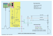
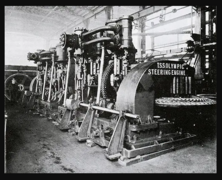
Anyhoo.. currently working on C deck and specifically the rudder engine room. As such I have built this computer model of the engines. Thought others might like so see. If you study the images you will see the control system. The demand is given as a turn angle on the shaft out front with the teal counterweight on it. That either lifts or pulls down the yoke on the economy valve which then high and low pressure steam pipe to the cylinders. Note: that's high and low .. or low and high... depending on which direction we need to move the rudder.
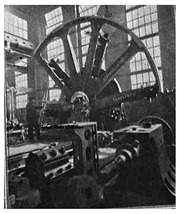
The pistons then do their thing cranking the big red wheel which delivers the turning motion to the rudder quadrant gear via a rather hi-tech and large spur gear arrangement. Another spur gear on the big red wheels shaft drives through the machine to the "front" and another spur spline gear .
Now the rod that goes through the yoke is threaded in the upper part and is threaded through the hole in the yoke. As such as the yoke is pushed up or pulled down the rod follows suit. The lower half of the rod is a spline which slides through the spur spline gear and is free to slide up and down through the gear as it turns.
So.. in a nutshell... the demand from the steering system pushes or pulls the yoke up or down, the machine then gets steam and begins to drive the shaft. This in turn is fed back to the spline which turns the valve rod so it screws through the yoke and effectively pulls or pushes the valve back to the closed position when the turn demand is met.
Enjoy
PS: This is as accurately as I can make it with the flat plate and dowels design rules I set. The design is as indicated on other drawings on this site and elsewhere. The description of how it works is all mine and based on my own extensive engineering background.
Last edited:


