Titanic's Reciprocating Engines

Mike, when Derek (OverWeightArchie) started this model about 2013 he mentioned that he was in the machinist business. When he got the first cylinders assembled he ran it on shop air but mentioned that until he worked out the lube system he'd have to limit the operations or he'd ruin the running surfaces. I see now that he has put oil holes in the cranks and eccentrics. It was mentioned at the time that scale lube pipes would be too narrow for oil to flow through.

Derek did mention using Teflon rings in the pistons which leaves me wondering how the Titanic cylinders were lubricated. Steam locomotives used hydrostatic lubricators (Google) for the valves and pistons but I don't see anything around the Titanic engines.

He has a Flickr collection at overweightarchie

Bill
 
Wow, Very nice collection!
But how many version of that engine he has produced ? (3 sets are visible in one of the picture in his collection).
And it seems that the one in the video mentionned in my previous conversation is a more recent version also more advanced, equiped with the turning device and thrust block.
 
I'm just going to quickly post this without responding to the latest conversations - I have a bit of a cold, so my head isn't working at full capacity :) ...This latest vid brings the previous images to life. @Bill West , as you can see I havent gotten around yet to correcting the link positions/angles but I will eventually!

Great stuff indeed. Can't wait when the turbine is included to.
 
@Cian O'Reilly
Being a very recent member, I have not yet had the opportunity to congratulate you on your huge work and this awesome 3D model that you are finalizing day by day.
It's really beautiful, especially with the animation.
Great Great Stuff ! Bravo!
I eagerly await your next publishings.
 
Hi, there,

I've two questions.

1- Regarding the oiling system

I think that a total-loss oiling system type was used for lubrication on reciprocating engines.

Oiling was made by gravity, using oil cups, oil boxes, syphons, wick feed lubricators, oil and grease brushes/combs, etc.. and also using some mechanical lubricators, but also, manually by oilers with oil burets and buckets of grease.

But where loose oil and greases where collected on the engines?

Was there any sump tanks provided in sole plates for such purposes?

2 - Regarding the cooling sytem (if any) for guide plates on columns for crosshead shoes.

Usually guide plates on columns for crossheads, generally made in cast iron, are secured on a hollow recess in the columns.
They are equipped with few oil-ways cut across the guide plates, with a lubricator at top and oil receiver at bottom out of which a comb/brush on the crosshead shoe picks up the oil and smears it over the guides.

Most always, guides are internally cooled with water.
Cooling water is admitted at bottom and discharge at top of the guides.

Do you know if such water cooling was provided on Titanic reciprocating engines guides, and if Yes, from which water system this colling system was connected ?
 
Cian -with the hull bottom in place in your latest video I started seeing a fat surfboard doing 80 knots across the waves with flames coming out of the exhaust : ) : ) : ) . It looks good.

JDD -Derek's project started with a block of duralumin that was left over from a work project (A380 aircraft parts). The size was just enough to start 3 engines in 1:60 scale. He completed 3 sets of bases and columns from the block but has only made the remaining parts for one of the engines (maybe the cylinders for the other 2 as well?). The assorted pictures over the years are the progress on the first engine.

I looked again at a high resolution copy of the turning engine picture. I'm thinking that the vertical lines on vertical shaft, each side of the upper bearing block, are just shine on a round shaft. Below the worm, rather than splines or a square shaft, there is a black line on the shaft that could be a keyway.

Lubrication was only oil, it all dripped into the crankcase pits. A pump pulled it through filters from the pits, ran it through coolers and sent it back up to gravity supply tanks. The head of the tanks gave 20 psi pressure. Some of the tank oil would be manually delivered to the many oil cups and boxes seen in Cian's pictures. I think of the pits as being dirty places but this circulation would actively remove fine dirt from them and with the oil being taken away, the coarse debris could be wiped out during port turn around. So despite the oil dripping to the pits and there being no supply pump this is still a circulating system with a pressure feed. The initial looks fooled me too.

I've not seen mention of cooling crosshead guides by water. In our case cooling the return oil covers the task.

Bill
 
Thanks Bill for your clarifications.

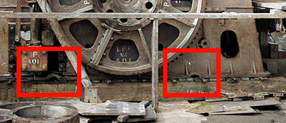
On Titanic and Britannic engines pictures taken at workshop ass'y , at bottom sides of the base plate under the crank shaft, we can see two half circle holes, just at ground level.
Same half circle holes can be found on front and rear parts of all base plates
Do you know what is the purpose of these openings , to drain oil ?
 

Attachments

  • Base_Plate_Engine_Half circle Openings.jpg
    Base_Plate_Engine_Half circle Openings.jpg
    167.5 KB · Views: 106
Those are to clear the overlap in the seams in the tank top plating. The top plate has an offset formed along one edge so that the rest of it will sit flat on the framing. The plate is referred to as having been joggled.

Bill
 
Thanks Bill, That's what I thought at first sight, but was not sure as I have no detail drawings of this area (and not shown on last Cian 3D drawings of tank top plating).

I want to come back to our previous conversation on water cooled crosshead guides on columns.

This afternoon I've watched again several videos on large marine steam engines, and on all of them I've been able to see their water cooling connections.
It seems strange for me that nothing similar was provided on Titanic and their sister engines.

Such type of arrangements are usual and described in many technical handbooks.

For example, In "The Marine Steam Engine" by R. Sennet & H.J. Oram (1898), at page 282 it is mentioned :
Crosshead guides are usually hollow on the ahead surface to enable a stream of cold water to be circulated through them.
Also mentionned and described with drawings in "Marine Engines and Boilers Handbooks" by Dr. G. Bauer (1905) page 206

To achive the cooling of crosshead guides only using the lubrication oil on this engine, in my opinion, it will require a very high flow rate of oil in such open circuit.

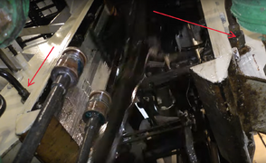
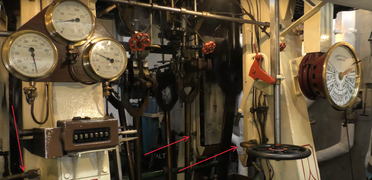
Here attached some pictures extracted from these videos.
 

Attachments

  • Steam_Engine_Cooling_water_INLET_on_crosshead_guides_1.jpg
    Steam_Engine_Cooling_water_INLET_on_crosshead_guides_1.jpg
    212.1 KB · Views: 93
  • Steam_Engine_Cooling_water_INLET_on_crosshead_guides_2.jpg
    Steam_Engine_Cooling_water_INLET_on_crosshead_guides_2.jpg
    267 KB · Views: 83
  • Steam_Engine_Cooling_water_INLET_on_crosshead_guides_3.jpg
    Steam_Engine_Cooling_water_INLET_on_crosshead_guides_3.jpg
    406.5 KB · Views: 93
  • Steam_Engine_Cooling_water_OUTLET_on_crosshead_guides_4.jpg
    Steam_Engine_Cooling_water_OUTLET_on_crosshead_guides_4.jpg
    276.6 KB · Views: 102
Those photos like very much have from the SS Shieldhall ship which is still in full operation today at Southampton. They must be the best people to answer your questions on lubrication and crosshead circulation. Though the two splendid working steam engines in Shieldhall were quite a bit smaller than Olympic/Titanic engines and built over 30 years later on, where new technology had moved on by quite a bit more.
The two big triple expansion engines at Kempton pumping station built in1926 where only gravity feed lubrication system. The lubrication oil tank does have a heater element when required. Far as crosshead circulation I don't see that at Kempton. But again they had move on with new technology of about 6-7 items over what was on the Olympic/Titanic engines.
 
You're wright, Mike.

Pictures 3 an 4 are taken from SS Shieldhall.

And Pictures 1 and 2 are taken from SS Jeremiah O'Brian (1943)

SS Jeremiah (Liberty Ship) is equipped with an triple expansion steam engine .
It is a vertical reciprocating triple expansion steam engine of 2,500 IHP with cylinder diameters of 24½” - 37” - 70” and a stroke of 48”, driving a single screw at 76 rpm for an average cruising speed of 11 knots.
 

Attachments

  • SS-Jeremiah-O'Brien_Triple_expansion_steam_Engine-1943.jpg
    SS-Jeremiah-O'Brien_Triple_expansion_steam_Engine-1943.jpg
    180.8 KB · Views: 105
The SS Shieldhall cylinder diameters 15" 25" 40" stroke 30" = 800 hp maximum speed 13 knots at 120 rpm. Normal speed is 9 knots at 86rpm..
Both ships are mazing to be in service today.
 
Good observation about the crosshead cooling JDD. I don't remember seeing it mentioned before and haven't spotted anything in the pictures and plans but now that I look deeply, a caption on TTSM pg.331 slips in a sentence about this. The figure there comes from H&W engineer C.C. Pounder's 1922 book "Machinery and Pipe Arrangement on Shipboard" pg.312. He describes the typical system as tapping off the salt water circulating supply to the condensers and just dumping the discharge in the bilges. He mentions cooling the crankshaft bearings as well.

In our case the general service salt water pumps in the engine room might be an easier source than drawing from the circulating pumps in the turbine room. I'm not sure about dumping the discharge in the bilge as that seems to require always having a bilge pump running. But I'm not sure of where else one could get the discharge to flow overboard. Accept it being non self-draining and give it its own high overboard discharge? Or include it in the auxiliary condenser discharge?

Bill
 
Hi Bill,

In "Handbook for Care and Operation of Naval Machinery by Lieut. H.C. Dinger (from US Navy)- 1908", at "Water Service" Chapter, page 77, it is writen the following interresting requirements :
Water Service.

Engines are fitted with a system of water
service by which cool sea water may be circulated through a bearing
or guide, or sprayed on any part liable to heating.
Collars of thrust bearings, main bearings and crosshead guides
are now usually cast hollow to allow for the circulation of water.
On some recent large engines the crossheads are fitted with a telescopic
water service to enable water to circulate through these.
In order to keep the large amount of water, which cornes through
the water service, out of the bilge and crank pits, some vessels
have the water service arranged so that the water which circulates
through the main bearings, guides and thrust bearings is led to the
suction of the circulating pump. As thus arranged, the water service
for these parts is a closed circuit.
There are usually a number of hose connections on the water
service so that a hose can be attached and cooling water led to any
desired place in engine room. These connections may also be used
in washing down the engine room.
The repair work that the water service will require consists of
grinding in its valves, tightening up on joints and unions and rebrazing
broken joints. .
The water service should be shut off about half an hour before
coming to an anchor so as to leave only clean oil on the surface of
the bearings when engines are stopped.
The following are the specifications for water service of recent
U. S. naval vessels.
"There will be in each engine room a 4-inch water-service pipe,
with a 4-inch branch to the main engine and a 2-inch branch to
the shaft alley, and smaller branches leading to different parts of
the engine and shaft, as follows:
One 1¼-inch branch with swivel joint for each crank-shaft bearing;
Two 1¼-inch pipes to each crank pin;
Two 1-inch pipes to each crosshead;
One 1-inch pipe to each go-ahead crosshead guide;
One 1-inch pipe to each pair of eccentrics;
One 1½-inch pipe to each thrust bearing;
One 1-inch pipe to each line-shaft bearing;
One t-inch pipe to each hollow brass or its equivalent in crankshaft
bearings;
Two 1-inch pipes to each air-pump engine and to each circulating
pump engine.
Each of the above branches will have a separate valve and will
terminate, as may be directed or approved, either in a pivoted nozzle,
a detachable spray nozzle, a short length of hose, or a permanent
connection to the part to be cooled.
The water-service pipe will be connected so as to take water
from the casing of the main circulating pump. There will be a stop
valve in the water-service pipe near the connection.
The water-service discharge pipes from crosshead guides, main
bearings and thrust bearing will connect to the suction side of the
main circulating pump, so that the water may pass overboard instead
of into the bilges.
There will be a system of water-service pipes for auxiliary machinery
in any part of the ship, as may be directed. These pipes
will be of approved size, thickness and arrangement, and will connect
with sea valves or pipes where directed."
 
Back
Top