Electricity During Sinking

Each emergency dynamo was driven at 380 revolutions per minute by a two-crank, compound engine with one HP and one LP cylinders. The emergency steam supply pipe that fed these engines ran along E deck above the watertight bulkheads and was arranged so it can take steam from the double-ended boilers in any of the three boiler rooms No. 2, 3, or 5. As a backup in case of accident to the main steam supply pipes, there was a connection that branched off of this emergency supply pipe to the pumps in the engine room that were connected to the bilges throughout the ship. There was also a cross connection to this pipe so that steam reaching the engine room from any boiler in the ship could be passed up to the emergency dynamos by opening two or three valves. A schematic of the main and auxiliary steam supply is shown in the diagram below.
View attachment 115458

Do you know of any available documentation on where the automatic closing valves in the main steam lines were? It's just my assumption they'd serve to sever the connection of the engines to the main steam lines on the basis there was one each plus three manual ones per line along boiler room bulkheads.
 
Do you know of any available documentation on where the automatic closing valves in the main steam lines were? It's just my assumption they'd serve to sever the connection of the engines to the main steam lines on the basis there was one each plus three manual ones per line along boiler room bulkheads.
From Sam's site below.
Steam from the boiler rooms was carried by two main steam pipes which passed through the watertight bulkheads to the reciprocating engine room. Shut-off valves were located at three of these bulkheads, including the one at bulkhead K going into the engine room. This was a quick-acting, balanced emergency valve fitted on each main steam pipe so that the steam could at once be shut off in case of a rupture in either one of the main pipes. On the after side of this bulkhead in the engine room were the main steam stop valves, 24-inches in diameter, each provided with a large separator and a cross connection. The separators were used in saturated steam lines to separate and remove any moisture formed because of heat losses. They worked by providing a series of changes in the direction of the steam flow and included a large surface area to intercept the droplets. The cross connection allowed either range of piping to be used for either or both engines. The main stop valves were operated by hand wheels and screws from the starting platform which was situated in the center of the forward end of reciprocating engine room near the bottom.
image011.jpg
 
From Sam's site below.
Steam from the boiler rooms was carried by two main steam pipes which passed through the watertight bulkheads to the reciprocating engine room. Shut-off valves were located at three of these bulkheads, including the one at bulkhead K going into the engine room. This was a quick-acting, balanced emergency valve fitted on each main steam pipe so that the steam could at once be shut off in case of a rupture in either one of the main pipes. On the after side of this bulkhead in the engine room were the main steam stop valves, 24-inches in diameter, each provided with a large separator and a cross connection. The separators were used in saturated steam lines to separate and remove any moisture formed because of heat losses. They worked by providing a series of changes in the direction of the steam flow and included a large surface area to intercept the droplets. The cross connection allowed either range of piping to be used for either or both engines. The main stop valves were operated by hand wheels and screws from the starting platform which was situated in the center of the forward end of reciprocating engine room near the bottom.
View attachment 115464
Thank you. I had missed that so far; I'd seen the mention of the automatic valves in the 1912 British report documentation.
 
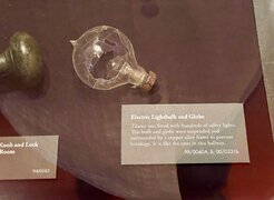
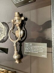
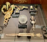
Here are some pictures of a grip fuse from Titanic, which was on display in Columbus, Ohio in spring and summer 2024. Additionally, there are light fixtures, also in Columbus. The light bulb was from the Titanic museum in Las Vegas. I took all these photos this year.
So, Bill West, you think the equaliser box seen here in the electrician https://www.encyclopedia-titanica.o...ic-and-titanic-part-i-july-28th-1-pdf.109674/ was above the lever interlock box on the platform floor, maybe slightly forward of the interlock box - connected by the rods we can see, on the lever box going up and forward. i agree thats possible. we dont have a view forward of the interlock lever frame, but we can see the interlock rods on the side views we have. that box appears to be a big thing... the electrician image shows it partially dissasembled... but the electrician doesnt say where that box was.. so that is why i asked you how you know it was where your diagrams show it... ive not found any confirming images or original mapping to be certain and why i asked you to give such a link that confirms its position - how it was accessed how it was mounted ( given its size ) etc... you know i have scaled that control room to the nearest foot... and the images we have looking from a point on the generator floor, give no hint of a central platform above the turbine prop shaft... ? for the rods for the interlock lever frame to connect with the box you have redesigned the platform to include a forward floor that i cant find any mapping of? BUt i agree ot makes sense given that all the power cables we can see in images of the control room, appear to be above the lever frame interlock box... and so i agree thats what the vertical poles were doing.. i can only agree that though in principle.. until i see evidence.. and i havent yet. ?
 

Attachments

  • T001 circut.jpg
    T001 circut.jpg
    1.1 MB · Views: 9
  • T002 circut.jpg
    T002 circut.jpg
    1.3 MB · Views: 15
  • T004.jpg
    T004.jpg
    2.7 MB · Views: 12
  • T005.jpg
    T005.jpg
    1.6 MB · Views: 15
  • T006.jpg
    T006.jpg
    1.2 MB · Views: 11
  • T003.jpg
    T003.jpg
    1.7 MB · Views: 14
Back
Top