Trevor G

Member
I have been working on developing plans to model Titanic with the aid of a Laser cutter to make flat plates for walls and floors and bits and bobs. I started at the boat deck and am working my way down... It's a ton of work lol.. Oh well.

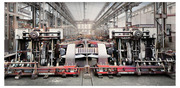
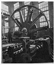
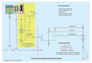
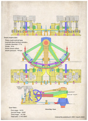
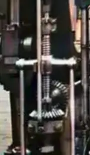
Anyhoo.. currently working on C deck and specifically the rudder engine room. As such I have built this computer model of the engines. Thought others might like so see. If you study the images you will see the control system. The demand is given as a turn angle on the shaft out front with the teal counterweight on it. That either lifts or pulls down the yoke on the economy valve which then high and low pressure steam pipe to the cylinders. Note: that's high and low .. or low and high... depending on which direction we need to move the rudder.

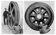
The pistons then do their thing cranking the big red wheel which delivers the turning motion to the rudder quadrant gear via a rather hi-tech and large spur gear arrangement. Another spur gear on the big red wheels shaft drives through the machine to the "front" and another spur spline gear .

Now the rod that goes through the yoke is threaded in the upper part and is threaded through the hole in the yoke. As such as the yoke is pushed up or pulled down the rod follows suit. The lower half of the rod is a spline which slides through the spur spline gear and is free to slide up and down through the gear as it turns.

So.. in a nutshell... the demand from the steering system pushes or pulls the yoke up or down, the machine then gets steam and begins to drive the shaft. This in turn is fed back to the spline which turns the valve rod so it screws through the yoke and effectively pulls or pushes the valve back to the closed position when the turn demand is met.

Enjoy

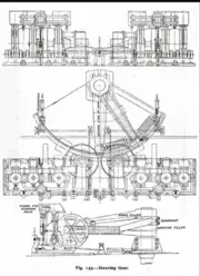
PS: This is as accurately as I can make it with the flat plate and dowels design rules I set. The design is as indicated on other drawings on this site and elsewhere. The description of how it works is all mine and based on my own extensive engineering background.


1678329566322.png
1678329591348.png
1678329613234.png
1678329646501.png
1678329686502.png

 
Last edited:
OH and by the way.. the whole engine is attached to horizontal jack screws at the front (Not shown) and is slid back out of the way when not in use, and flange plates are used to connect the demand shaft to the telemotor. Can we say "brute force engineering..." lol
 
Putting it all together... one engine engaged the other not, (pulled back) and with the telemotor rod disconnected. I also included a zipped "Blender" file if you want to play with it in 3D.


Attachments

  • Steering Engine.zip
    3.1 MB · Views: 66
Last edited:
Hello,

Nice Blender modeling.

What's the content of your two above videos you have posted here, because they are not visible? Only toolbars appears visibles but not the content (view from my computer)?

You may try to post them again.

Just a comment :

To reduce mainly noises and vibrations, all gears (spur and bevel) on the steering engines where of double herringbone type (Citroën) and not straight type as in your 3D blend file.

It's a bit more difficult for modeling them but they will be more realistic.

See attached pictures.
 

Attachments

  • SS_Britanic_Steering_Engine_at_workshop_color.jpg
    SS_Britanic_Steering_Engine_at_workshop_color.jpg
    755.1 KB · Views: 82
  • Titanic_Citroen_double_herringbone_Stearing_Spur and Bevel_Gears.jpg
    Titanic_Citroen_double_herringbone_Stearing_Spur and Bevel_Gears.jpg
    465.1 KB · Views: 76
Last edited:
To reduce mainly noises and vibrations, all gears (spur and bevel) on the steering engines where of double herringbone type (Citroën) and not straight type as in your 3D blend file.

It's a bit more difficult for modeling them but they will be more realistic.
Yes I know... and beyond my blender ability I am afraid.. But Its only meant to be representative, not accurate.
 
1678571954075.png
1678571977574.png
1678572015358.png
1678572077511.png


For those that cant see the MP4 videos.

BTW: Note the teal worm gear on the dummy steering wheel attached to the shaft that runs up to the wheel on the aft bridge. That lot would be disconnected for normal operation by undoing those flanges either side of them.

The fact that it is a worm gear, which can not be back driven, and not a spur gear, which can, it very much proves the aft steering position was for emergency use only. It would be used if all else failed and would require someone to connect the flanges and disconnect the telemotors.
 
I agree. I think, it's more for having minimum wear in both direction and keeping more precision.

Personally I've never seen such kind of double herringbone gears on other industrial transmission.
 
Hi There,

Hello Trevor,

I'm coming back to the captioned subject.

STEAM CONTROL VALVE

Your explanation on how the steam control valve is operated is a little bit difficult to understand from my point of view but I know it's not easy to explain in detail how such vintage device is working.

The majority of patent steering gear engines of that time were fitted with three valves, a central control valve and two piston valves one for each

cylinder of the engine.

The control valve distributes the steam to the engine valves so that the gear may run either to port or starboard as required.

In this case each piston valve requires only one eccentric, the control valve acting as the reversing gear.

The piston valves have no steam lap, so that the steam is carried for the full length of the piston stroke.

The eccentric keyseats are cut at right angles to the cranks.

The control valve is operated directly by the telemotor linked with the steering wheel on the bridge, and also automatically by a counteracting

return gear from crank-shaft of the steering engine.

Here attached a colored schematic drawing I've produced for my own needs and my own understanding of the Olympic Class steering Engine

which may be help for a better knowledge of this device.

If there's any mistakes, please don't hesitate to let me know

QUADRANT ARRANGEMENT

I've examined in more detail your 3D drawing, and I' dont know from where you've got information to produced such kind of arrangement.

The only one drawing I know of the Olympic Class Steering Gear is the one published in 1911 in The Shipbuilder (The Shipbuilder Mauretania,

Olympic & Titanic Souvenir Numbers) and also reproduced in TTSM volume 1

Here the link to this document : Here

The cast steel quadrant is made in 2 parts half parts and has 5 arms (see attached picture of the olympic quatrant during machining)

The half parts are connected together by bolts in the middle axis of the third arm (splited in two)

The gear quadrant (in one piece) is bolted on the front of the quadrant

The quadrant is mounting loose on the rudder headshaft.

Due to the canteliver arrangement of the quadrant, and to conterbalance the bending effect due to his heavy weight, the quadrant is supported

by two taper rollers acting on a machined path at the bottom head of the quadrant.

Two forged working tillers are provided and are keyed on the rudder headshaft

Each arm is placed at the centre of each half of the quadrant and is connected elastically to the quadrant by means of a pair of strong springs

The working tillers are located under the quadrant

One spare forged tiller keyed on the rudder headshaft in placed over the quadrant and connected with tie bars to the quadrant

Here attached a colored drawing I've produced and completed for my own needs and my own understanding which also may be helpfull for a

better knowledge of this device.

Again, If there's any mistakes, please don't hesitate to let me know
 

Attachments

  • Olympic Steering Quadrant_at_machining_workshop.jpg
    Olympic Steering Quadrant_at_machining_workshop.jpg
    158.6 KB · Views: 72
  • Olympic_Class_Steering_Gear_Schematic.jpg
    Olympic_Class_Steering_Gear_Schematic.jpg
    555.5 KB · Views: 68
  • Titanic_Steering_Engine_Color.jpg
    Titanic_Steering_Engine_Color.jpg
    1.8 MB · Views: 145
that is pretty much what my model shows... I used that drawing too, or a version of it. The issue with those drawings is they show the mechanism in different positions in the one drawing so it gets confusing.
The rest of it is taken from that and inspecting the images shown below.

The eccentrics are not shown on the schematics but are clearly visible in the colourised versions and the shape of the piston boxes also indicates that each has its own set of valves. The Big valve on the front simply supplies steam Hi-Lo pressure as dictated by the demand and that screw yoke arrangement I mentioned which is easy to see on the colour image.... see inset,

Also be aware I cam seeing some big differences between the three ships.


That bit about the spare tiller being connected to the quadrant with tie-bars makes no sense as it negates the use of the springs.
 

Attachments

  • 4790d51e3f0e0c4fe08d659332ab455e.jpg
    4790d51e3f0e0c4fe08d659332ab455e.jpg
    138.2 KB · Views: 62
  • Screenshot_1.png
    Screenshot_1.png
    331.1 KB · Views: 48
  • Screenshot_2.png
    Screenshot_2.png
    3.3 MB · Views: 49
  • Screenshot_3.png
    Screenshot_3.png
    608.4 KB · Views: 62
  • Screenshot_4.png
    Screenshot_4.png
    510.2 KB · Views: 64
Last edited:
Hi There,

Hello Trevor,

I'm coming back to the captioned subject.

STEAM CONTROL VALVE

Your explanation on how the steam control valve is operated is a little bit difficult to understand from my point of view but I know it's not easy to explain in detail how such vintage device is working.

The majority of patent steering gear engines of that time were fitted with three valves, a central control valve and two piston valves one for each

cylinder of the engine.

The control valve distributes the steam to the engine valves so that the gear may run either to port or starboard as required.

In this case each piston valve requires only one eccentric, the control valve acting as the reversing gear.

The piston valves have no steam lap, so that the steam is carried for the full length of the piston stroke.

The eccentric keyseats are cut at right angles to the cranks.

The control valve is operated directly by the telemotor linked with the steering wheel on the bridge, and also automatically by a counteracting

return gear from crank-shaft of the steering engine.

Here attached a colored schematic drawing I've produced for my own needs and my own understanding of the Olympic Class steering Engine

which may be help for a better knowledge of this device.

If there's any mistakes, please don't hesitate to let me know

QUADRANT ARRANGEMENT

I've examined in more detail your 3D drawing, and I' dont know from where you've got information to produced such kind of arrangement.

The only one drawing I know of the Olympic Class Steering Gear is the one published in 1911 in The Shipbuilder (The Shipbuilder Mauretania,

Olympic & Titanic Souvenir Numbers) and also reproduced in TTSM volume 1

Here the link to this document : Here

The cast steel quadrant is made in 2 parts half parts and has 5 arms (see attached picture of the olympic quatrant during machining)

The half parts are connected together by bolts in the middle axis of the third arm (splited in two)

The gear quadrant (in one piece) is bolted on the front of the quadrant

The quadrant is mounting loose on the rudder headshaft.

Due to the canteliver arrangement of the quadrant, and to conterbalance the bending effect due to his heavy weight, the quadrant is supported

by two taper rollers acting on a machined path at the bottom head of the quadrant.

Two forged working tillers are provided and are keyed on the rudder headshaft

Each arm is placed at the centre of each half of the quadrant and is connected elastically to the quadrant by means of a pair of strong springs

The working tillers are located under the quadrant

One spare forged tiller keyed on the rudder headshaft in placed over the quadrant and connected with tie bars to the quadrant

Here attached a colored drawing I've produced and completed for my own needs and my own understanding which also may be helpfull for a

better knowledge of this device.

Again, If there's any mistakes, please don't hesitate to let me know
see my next post..
 
The cast steel quadrant is made in 2 parts half parts and has 5 arms (see attached picture of the olympic quatrant during machining)
This is interesting news though. though makes the side view a tad difficult to understand how the quadrant and tiller dont interfere.. I will play with that in my model though... It did seem odd it was so isometric. Thinking the tie bars might actually be slide bars to limit the spring compression distance.
 
Last edited:
Back
Top